


1-21
Catalyst 3850 Switch Hardware Installation Guide
OL-26779-02
Chapter 1 Product Overview
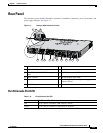
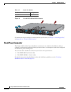
Rear Panel
The power supply modules have two status LEDs.
For information about replacing a power supply module, wiring a DC power supply module, and module
specifications, see Chapter 4, “Power Supply Installation,” and Appendix A, “Technical Specifications.”
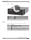
Fan Modules
The switch has three internal hot-swappable 12-V fan modules. The air circulation system consists of
the fan modules and the power supply modules. The airflow patterns vary depending on the power supply
configuration.
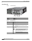
Figure 1-8 shows the airflow patterns for the 24- and 48-port switches. The blue arrow shows cool air
flow, and the red arrow shows warm air flow. When the fan modules are operating properly, a green LED
is on at the top left corner of the fan assembly (viewed from the rear). If the fan fails, the LED turns to
amber. The switch can operate with two operational fans, but the failed fan should be replaced as soon
as possible to avoid a service interruption due to a second fan fault.
Note Three fans are required for proper cooling.
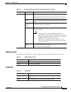
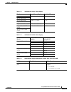
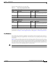
Table 1-16 Switch Power Supply Module LEDs
AC-Power Supply Module LEDs
AC OK Description PS OK Description
Off No AC input power. Off Output is disabled, or input is
outside operating range (AC LED
is off).
Green AC input power present. Green Power output to switch active.
Red Output has failed.
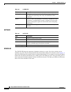
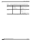
DC-Power Supply Module LEDs
DC OK Description PS OK Description
Off No DC input power. Off Output is disabled, or input is
outside operating range (DC LED
is off).
Green DC input power present. Green Power output to switch active.
Red Output has failed.