


Chapter 3 Installing the Switch in a Rack
System Ground Connection Guidelines
3-18
Catalyst 4500 Series Switches Installation Guide
78-14409-08
Step 6 Connect the switch to an appropriate ground. Refer to System Ground Connection
Guidelines, page 3-18. The system must have a ground connection before power
is supplied to the switch.
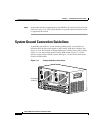
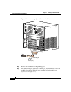
System Ground Connection Guidelines
A grounding pad with two system (earth) grounding holes is provided in an
enclosure near the left power supply on the Catalyst 4500 series switches. See
Figure 3-13 for the location of the grounding holes on the Catalyst 4503 switch,
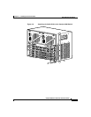
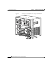
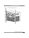
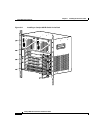
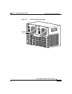
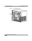
Figure 3-14 for the location on the Catalyst 4506 switch, Figure 3-15 for the
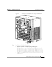
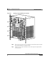
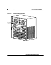
location on the Catalyst 4507R switch, and Figure 3-16 for the location on the
Catalyst 4510R switch.
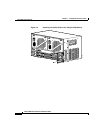
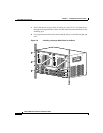
Figure 3-13 Catalyst 4503 Grounding Holes
1
1
3
1
1
3
1
1
3
1
1
3
79479
4
5
0
6
U
P
L
I
N
K
1
U
P
L
I
N
K
2
A
C
T
I
V
E
L
I
N
E
A
C
T
I
V
E
L
I
N
E
A
C
T
I
V
E
R
E
S
E
T
U
T
I
L
I
Z
A
T
I
O
N
S
T
A
T
U
S
4
5
0
3
W
S
-
X
4
5
1
5
S
U
P
E
R
V
I
S
O
R
E
N
G
I
N
E
I
V
1
%
1
0
0
%
C
O
N
S
O
L
E
L
I
N
K
E
J
E
C
T
F
L
A
S
H
1
0
/
1
0
0
M
G
T
Grounding
holes (2)