


3-5
Catalyst 4500 Series Switches Installation Guide
78-14409-08
Chapter 3 Installing the Switch in a Rack
Rack-Mounting the Switch
Note Some equipment racks provide a power strip along the length of one of
the rear posts. If your rack has this feature, consider the position of the
strip when planning fastener points. Before installing the L brackets on
the chassis, determine whether to install the chassis from the front or the
rear of the rack.
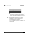
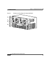
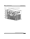
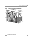
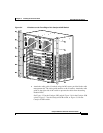
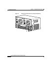
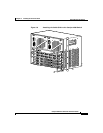
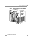
Step 2 Install the L brackets, which connect the chassis to the rack, as follows:
a. Remove the screws from the front of the switch side-cover panels.
b. Attach the left and right L brackets using the six M4 Phillips pan-head screws
(three screws per side) provided in the rack-mount kit.
See Figure 3-1 for the Catalyst 4503 switch, Figure 3-2 for the Catalyst 4506
switch, or Figure 3-3 for the Catalyst 4507R switch, or Figure 3-4 for the
Catalyst 4510R switch.
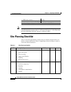
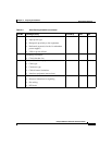
Table 3-1 Rack-Mount Kit Checklist
Quantity Part Description
2L brackets
6 M4 Phillips pan-head screws
6 12-24 x 3/4-inch Phillips binder-head screws