


Chapter 4 Removing and Replacing FRUs
Removing and Replacing the Chassis Fan Assembly
4-18
Catalyst 4500 Series Switches Installation Guide
78-14409-08
Step 8 Verify power supply operation by checking the power supply’s front-panel LEDs.
You should see the following:
• The LED labeled INPUT OK is green.
• The LED labeled OUTPUT FAIL is not lit.
Step 9 Check the power supply and system status from the system console by entering
the show system command (Catalyst Operating System) or the show power
command (Cisco IOS). For more information on these commands, refer to the
command reference publication for your switch and software.
Step 10 If the LEDs or the show system command (Catalyst Operating System) or the
show power command (Cisco IOS) output indicate a power problem or other
system problem, see Chapter 5, “Troubleshooting,” for more information.
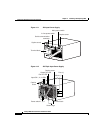
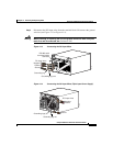
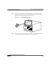
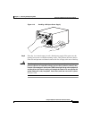
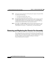
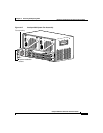
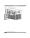
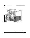
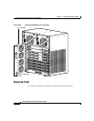
Removing and Replacing the Chassis Fan Assembly
This section describes how to remove and install the chassis fan assembly for the
Catalyst 4500 series switches. See Figure 4-17 for the Catalyst 4503 system fan
assembly, Figure 4-18 for the Catalyst 4506 system fan assembly, Figure 4-19 for
the Catalyst 4507R system fan assemblies, and Figure 4-20 for the
Catalyst 4510R system fan assemblies.