


3-25
Catalyst 4500 Series Switches Installation Guide
78-14409-08
Chapter 3 Installing the Switch in a Rack
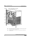
System Ground Connection Guidelines
Ensure that the grounding lug and the attached wire will not interfere with other
switch hardware or rack equipment.
Step 7 Tighten the screws to secure the grounding lug to the grounding pad.
Step 8 Repeat steps 1 through 3 to prepare the other end of the grounding wire and
connect it to an appropriate grounding point at your site to ensure adequate earth
ground for the switch.
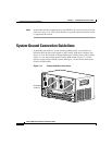
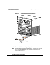
Step 9 Connect the power supply cords.
The switch comes on when the cords are connected and the power supply on/off
switch is on.
Note This equipment is suitable for connection to intra-building wiring only.
Note If you are using a DC power supply, the DC return connection to this system
should remain isolated from the system frame and chassis (DC-I).
This completes the installation of the Catalyst 4500 series switches.
At this point you should use the RJ-45-to-RJ-45 rollover cable to connect the
console port to a PC that runs terminal emulation software. Configure your
terminal emulation program for 9600 baud, 8 data bits, no parity, and 1 stop bit.
With this console connection, you can configure the switch as discussed in the
software configuration guide appropriate for your switch’s software release, and
monitor the software as the switch goes through its startup routine. The pinout for
the console port is detailed in the module installation guide at:
http://www.cisco.com/univercd/cc/td/doc/product/lan/cat4000/hw_doc/mod_inst
/0aspecs.htm#wp1003732