


Chapter 1 Product Overview
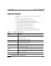
Supervisor Engines
1-24
Catalyst 4500 Series Switches Installation Guide
78-14409-08
• CONSOLE Port, page 1-26
• RESET Button, page 1-26
• CompactFlash Port, page 1-27
LEDs
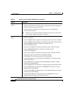
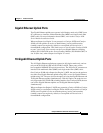
Table 1-6 describes the supervisor engine LEDs.
Table 1-6 Supervisor Engine LEDs
LED Color/State Description
STATUS Indicates the results of a series of self-tests:
Green All diagnostic tests passed.
Red A test failed.
Orange System boot or diagnostic test is in progress.
Off Module is disabled.
UTILIZATION Green 1–100% If the switch is operational, this display indicates the current
traffic load over the backplane (as an approximate percentage).
LINK Indicates the status of the 10/100BASE-T port,
10/100/1000BASE-T or uplink ports:
Green The link is operational.
Orange The link is disabled by user.
Flashing orange The power-on self-test indicates a faulty port.
Off No signal is detected or there is a link configuration failure.
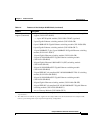
ACTIVE Indicates whether the uplink port is active or not:
Green The port is active.
Off The port is not active.
ACTIVE The LED to the right of the uplink ports is only used in switches
with two supervisors. The LED lights on the active supervisor.