


5-6
Catalyst 4500 E-Series Switches Installation Guide
OL-13972-01
Chapter 5 Troubleshooting
Troubleshooting the Fan Assembly
If the show module command output shows a message that states "not enough power for module," check
the
“Catalyst 4500 Power Supplies” section on page A-6 for the minimum power requirements for the
power supply. There may be a problem with the power source itself.
Power Supply Mixing
The 1400 W DC multi-input supply can not be used with other power supply types, but other power
supplies in this product line work with the other types during an upgrade. If you mix power supplies in
a Catalyst 4500 series chassis, the switch detects the type of power supply in power supply bay 1 (PS1)
and ignores the power supply in power supply bay 2 (PS2) while issuing system messages and showing
the power supply in bay 2 as in the err-disable state in the output of the show power command. When
the power supply in bay 1 is removed, the switch recognizes the power supply in bay 2, and you may
then put a new matching power supply in bay 1. Both supplies should resume normal function.
Troubleshooting the Fan Assembly
Note All fans must be operating or a failure will occur.
Environmental problems may initially appear to be problems with the fan tray. To help isolate a fan
assembly problem, follow these steps:
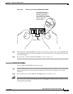
Step 1 Check the status LED on the fan tray.
• If the LED is off and the rest of the system is functioning, the fan tray is not getting power or is not
seated correctly on the backplane.
• If the LED is green, the fans are operating normally. There may be conditions impairing fan
performance, but they are minimal in impact.
• If the LED is red, one or more fans have failed.
Step 2 Connect a terminal and determine the fan tray status shown by the show environment status CLI
command. The status and sensor columns should say good.
Step 3 Determine whether the airflow is restricted or if the ambient temperature in the room is too warm.
Step 4 Determine whether the power supply is functioning properly. See the “Troubleshooting the Power
Supply” section on page 5-4.
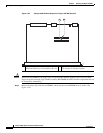
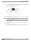
Step 5 Verify that the fan assembly is properly seated in the backplane by loosening the captive installation
screws, removing the fan assembly, and reinstalling it.
Step 6 Restart the system.
Step 7 Verify that all fans are operating. You should hear the fans at system start.
Step 8 If the system is still detecting a fan assembly failure, check for details using the CLI and contact the
Cisco TAC for assistance.