


2-11
Catalyst 4500 E-Series Switches Installation Guide
OL-13972-01
Chapter 2 Preparing for Installation
Site-Planning Checklist
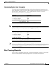
Calculating System Heat Dissipation
To calculate the expected heat dissipation from a switch, add the total amount of power drawn from
power supply by the system's configuration, then divide the total amount of power by the efficiency of
the power supply. Multiply the result by 3.415 to get the system heat dissipation in BTUs/hr.
First example (System without any powered devices):
Note All power supplies have different efficiencies, An average efficiency figure of 75% was chosen.
Second example (same system but this time with one IEEE class 3 device):
Note Although a class 3 device needs 15.4 W to power up, 17.3 W need to be generated from the backplane
in order to have 15.4 W at the switch port. 17.3 W comes from the WS-X4248-RJ45V DC-DC
converter’s efficiency (89%).
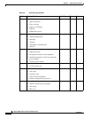
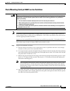
Site-Planning Checklist
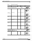
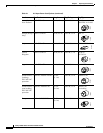
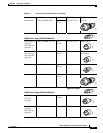
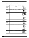
Table 2-2 lists the site-planning activities that you should complete before you install a Catalyst 4500
E-series switch. Completing each activity helps to ensure a successful switch installation.
Components
Output Power
1 - Catalyst 4506-E with fans 50 W
1 - Supervisor Engine IV 145 W
1 - WS-X4248-RJ45V with no phones 72 W
total output power 267 W
Total heat dissipated by system = (267/.75) * 3.415 = 1215 BTUs/hr
Components
Output Power
1 - Catalyst 4506-E with fans 50 W
1 - Supervisor Engine IV 145 W
1 - WS-X4248-RJ45V with no phones 72 W
1 - IEEE class 3 device 17.3 W
total output power 284 W
Total heat dissipated by system = (284/.75) * 3.415 = 1293 BTUs/hr