


1-8
Catalyst 4500 E-Series Switches Installation Guide
OL-13972-01
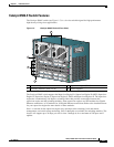
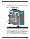
Chapter 1 Product Overview
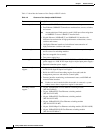
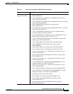
Switch Features
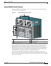
Supervisor Engine Redundancy
The Catalyst 4507R-E and Catalyst 4510R-E switches support supervisor engine redundancy.
Redundancy allows a second supervisor engine to take over if the active supervisor engine fails.
With supervisor engine redundancy enabled, if the active supervisor engine fails or if a manual
switchover is performed, the redundant supervisor engine becomes the active supervisor engine. The
redundant supervisor engine is automatically initialized with the startup configuration of the active
supervisor engine. Depending on the configuration this shortens the switchover time from 30 seconds or
longer in Route Processor Redundancy (RPR) mode, to less than a second in Stateful Switch Over (SSO)
mode.
In addition to the reduced switchover time, supervisor engine redundancy supports these:
• Online insertion and removal (OIR) of the redundant supervisor engine
Supervisor engine redundancy allows OIR of the redundant supervisor engine for maintenance.
When the redundant supervisor engine is inserted, the active supervisor engine detects it. The
redundant supervisor engine boots into a partially initialized state in RPR mode and a fully
initialized state in SSO mode.
• Software upgrade
Load the new image on the redundant supervisor engine and conduct a switchover. This minimizes
downtime during software changes on the supervisor engine.
When power is first applied to a switch, the supervisor engine that boots first becomes the active
supervisor engine and remains active until a switchover occurs.
Redundancy requires that both supervisor engines in the chassis are of the same supervisor engine
model, and that they use the same Cisco IOS software image.
For more detail about redundancy, refer to the Configuring Supervisor Engine Redundancy Using RPR
and SSO chapter of the software configuration guide for your software release.
1. You will need to configure the 1400 W DC input current as appropriate for the model of switch. Refer to Appendix A,
“Specifications.”