


16
Installation and Configuration Note for the Catalyst 4500 Series Supervisor Engine V
78-15590-02
Installing and Removing the Supervisor Engine
Removing the Supervisor Engine
Warning
Invisible laser radiation may be emitted from disconnected fibers or connectors. Do not stare into
beams or view directly with optical instruments.
Statement 1051
Warning
Hazardous voltage or energy is present on the backplane when the system is operating. Use caution
when servicing.
Statement 1034
Caution To prevent ESD damage, handle supervisor engines by the carrier edges only.
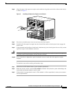
To remove a supervisor engine from a Catalyst 4500 series switch, follow this procedure:
Step 1 Disconnect any network interface cables attached to the ports on the supervisor engine that you intend
to remove.
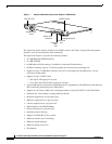
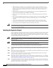
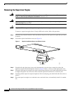
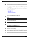
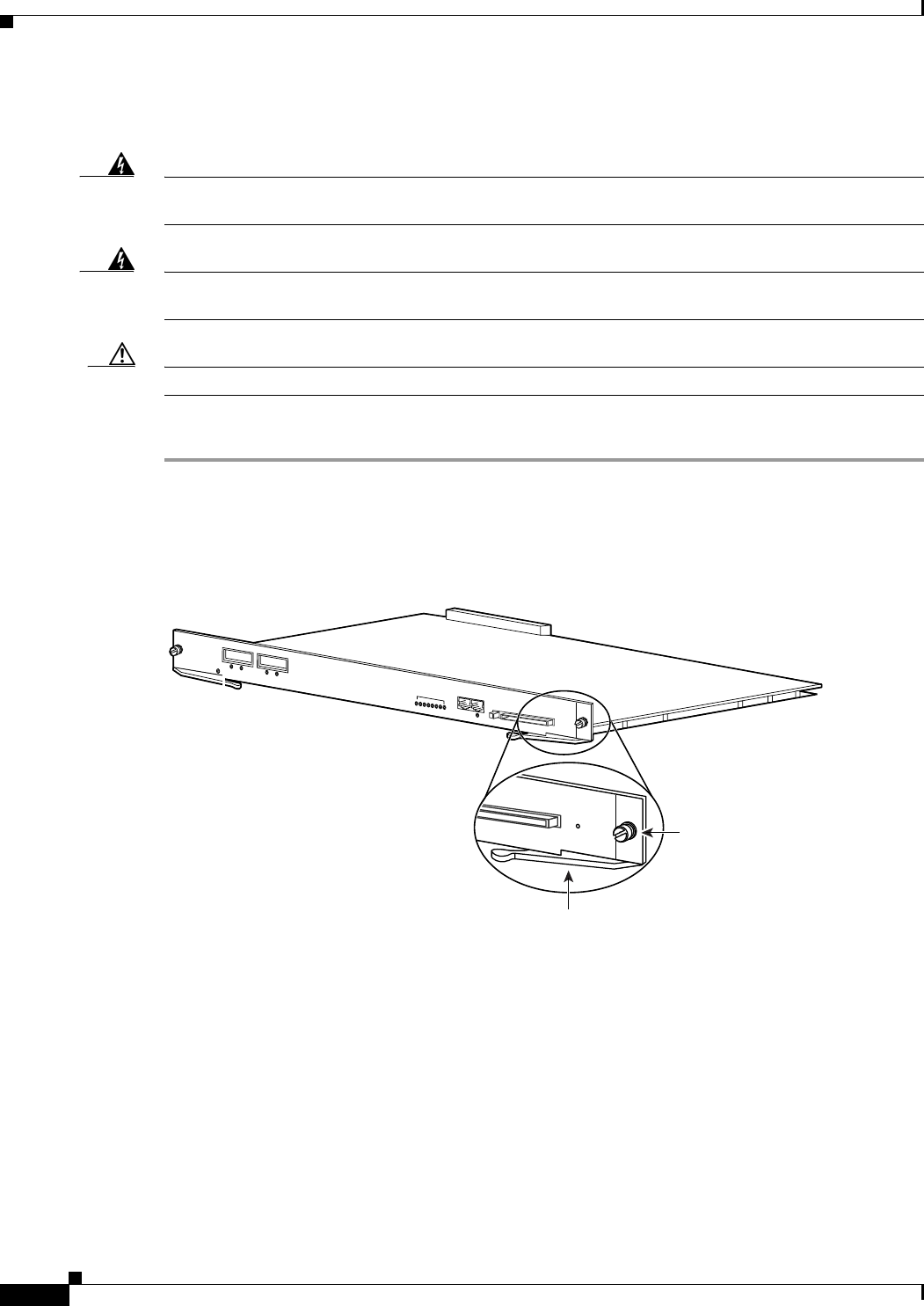
Step 2 Loosen the captive installation screws (see Figure 3).
Figure 3 Captive Installation Screws and Ejector Levers
Step 3 Grasp the left and right ejector levers and simultaneously pivot the levers outward to release the
supervisor engine from the backplane connector. Figure 3 shows a close-up of the right ejector lever.
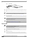
Step 4 Grasp the front panel of the supervisor engine with one hand and place your other hand under the carrier
to support and guide it out of the slot. Do not touch the printed circuit boards or connector pins.
Step 5 Carefully pull the supervisor engine straight out of the slot, keeping your other hand under the carrier to
guide it.
Step 6 Place the supervisor engine on an antistatic mat or antistatic foam, or immediately install it in another
slot.
68143
U
P
LIN
K
1
LIN
K
A
C
TIV
E
LIN
K
AC
T
IV
E
U
P
LIN
K
2
C
O
N
S
O
L
E
1
0
/1
0
0
M
G
T
E
J
E
C
T
F
L
A
S
H
U
T
IL
IZ
A
T
IO
N
S
T
A
T
U
S
S
U
P
E
R
V
IS
O
R
III E
N
G
IN
E
W
S
-X
4
0
1
4
1%
100%
Captive
installation
screw
Ejector lever
FLASH
RESET