


9
Installation and Configuration Note for the Catalyst 4500 Series Supervisor Engine V
78-15590-02
Supervisor Engine V
• Supervisor engine redundancy between primary and standby supervisor engines in Catalyst 4510R
and Catalyst 4507R
• 802.1Q tunneling
• Storm control in hardware
• Support for the Catalyst 4500 Series NetFlow Services Card (WS-F4531).
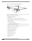
When the Supervisor Engine V is used in a Catalyst 4510R, slot 10 is a flex-slot intended for use with
the 2-port Gigabit Ethernet switching module (WS-X4302-GB) or the Access Gateway Module
(WS-X4604-GWY) only.
Features of the Supervisor Engine Front Panel
The following sections describe the LEDs, connectors, and switches on the Catalyst 4500 series
Supervisor Engine V:
• LEDs, page 9
• Gigabit Ethernet Uplink Ports, page 10
• Ethernet Management Port, page 10
• Console Port, page 10
• Reset Button, page 10
• Flash Port, page 11
LEDs
Table 1 describes the LEDs on the supervisor engine front panel.
Table 1 Supervisor Engine LEDs (WS-X4516)
LED LED Status Description
STATUS Indicates the results of a series of self-tests.
Green All diagnostic tests passed.
Red A test failed.
Orange System boot or diagnostic test is in progress.
Off Module is disabled.
UTILIZATION Green 1–100% If the switch is operational, this display indicates the current
traffic load over the backplane (as an approximate percentage).
Link Indicates the status of the 10/100BASE-T Ethernet management
port or uplink ports.
Green The link is operational.
Orange The link is disabled by user.
Flashing orange The power-on self-test indicates a faulty port.
Off No signal is detected or there is a link configuration failure.