


— 17 —
CAUTION!
DO NOT connect any other device than the specified cash drawer to the cash drawer
kick-out connector. (Also DO NOT connect a telephone line.)
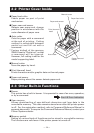
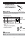
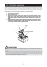
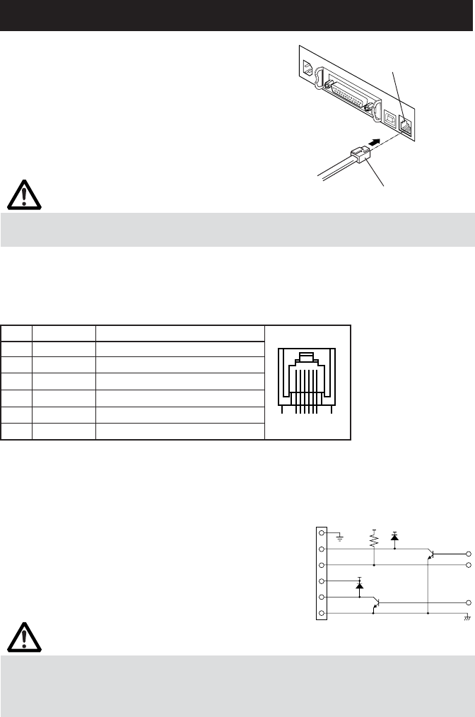
3.3 Connecting the Cash Drawer
Cash drawer
kick-out connector
Cash drawer cable connector
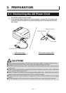
1. Confirm that the power switch is OFF.
2. Confirm the top and bottom of the cash
drawer cable connector and insert it into
the cash drawer kick-out connector at the
back of the printer.
3. Screw the cash drawer's ground wire to the
body of the printer.
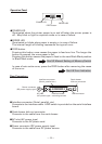
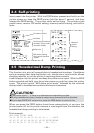
(1) Connector Pin Configuration
(2) Electrical characteristics
1) Driving voltage: 24 VDC
2) Driving current: Approx. 1A max. (shall not exceed 510 ms.)
3) DRSW signal: Signal levels: “L” = 0 to 0.5 V, “H” = 3 to 5 V
(3) DRSW signal
DRSW signal status can be tested with
the DLE+EOT, GS+a, or GS+r command or
at pin 34 on the parallel interface port.
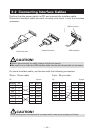
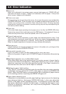
(4) Drive Circuit (printer side)
No. Signal Function
1FG Frame Ground
2 DRAWER 1 Drawer 1 drive signal
3 DRSW Drawer switch input
4 VDR Drawer drive power supply
5 DRAWER 2 Drawer 2 drive signal
6 GND Common ground on circuits
61
Connector used:
TM5RJ3-66 (Hirose)
or equivalent
Applicable connector:
TM3P-66P (Hirose) or
equivalent
CAUTION!
■ No output is produced while printing.
■ The cash drawers 1 and 2 cannot be driven simultaneously.
■ A solenoid used for the cash drawer should be of 24 Ω or more. The output current
should be kept at 1A or less; otherwise, breakdown or burning could occur.
VDR
1
2
3
4
5
6
VDR
5V