


iDP-3540/41 User’s Manual
CITIZEN 20/48
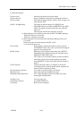
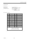
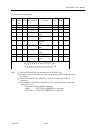
8-3. Description of Input / Output Signals
8-3-1. Input / Output Signals
a) Input / Output Signals
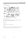
*DATA : 8 bit parallel signal. (Positive logic)
*STB : A strobe signal for reading in 8 bit data. (Negative logic)
*RESET : A signal which resets the entire printer. (Negative logic, 1 ms or more)
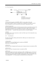
b) Output Signals (From Printer)
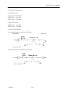
*ACK : This is a pulse signal for requesting 8 bit data, issued at the end of a BUSY
signal. (Negative logic)
*BUSY : This signal indicates that your printer is in a BUSY state.
New data should be input when this signal is “LOU”. (Positive logic)
*FAULT : When your printer is in an alarm state, this signal is “LOW”. At this time,
all control circuits of your printer are interrupted. (Negative logic)
Note: An alarm condition occurs when the timing of the print head movement sensor is abnormal.
c) Power Source
*”H” Level : H level out put for TTL level
*GND : The common circuit ground.
*FRAME GND : Connect the shield of interface cable to this.