


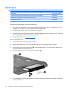
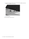
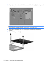
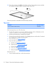
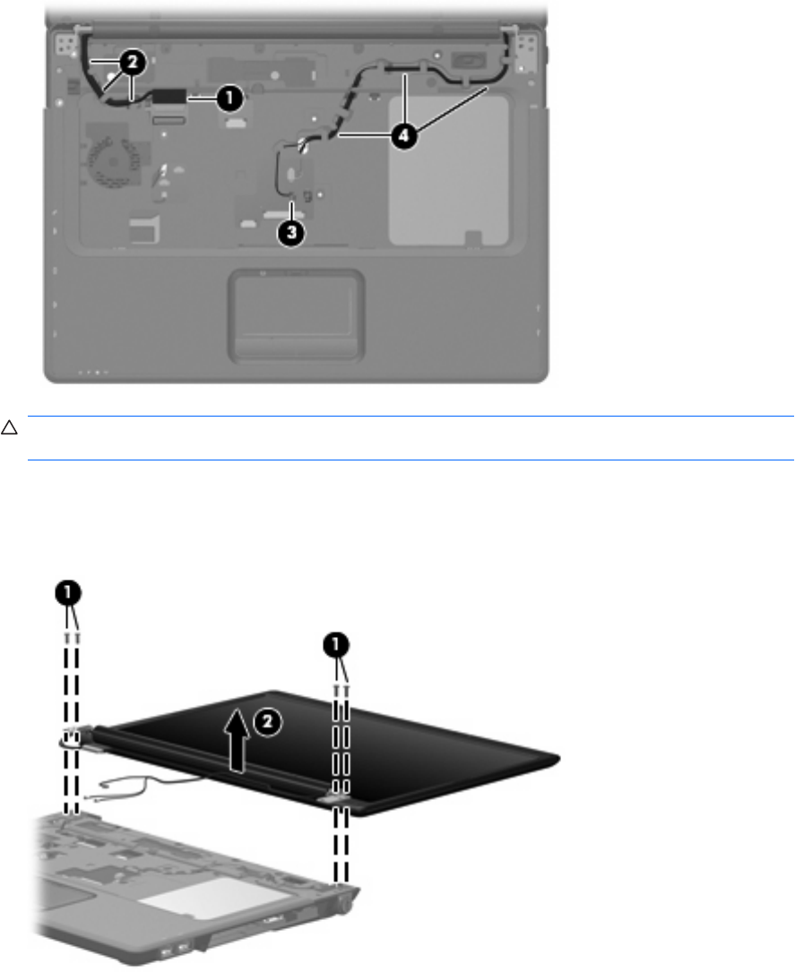
3. Remove the microphone cable and the WLAN antenna cables from the clips (4) and routing channel
built into the top cover.
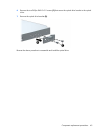
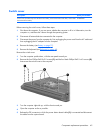
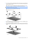
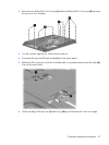
CAUTION: The display assembly will be unsupported when the following screws are removed. To
prevent damage to the display assembly, support it before removing the screws.
4. Remove the four black Phillips PM2.5×9.0 screws (1) that secure the display assembly to the
computer.
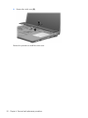
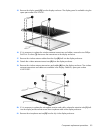
5. Remove the display assembly (2).
52 Chapter 4 Removal and replacement procedures