Using the System Control Manager 8-21
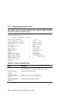
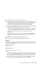
For QBB0:
Px.x indicates that a remote I/O riser is present (P), but no I/O mapping
(x.x) has been determined.
P2.0 indicates that a hose from local I/O riser 2, port 2, (IOR2) is connected
to PCI box 2, remote I/O riser 0.
Pf.1 indicates that a hose from local I/O riser 1, port 1 (IOR1) is connected
to PCI box F, remote I/O riser 1.
Pf.0 indicates that a hose from local I/O riser 1, port 0 (IOR0) is connected
to PCI box F, remote I/O riser 0.
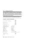
Global port module self-test results.
QBB backplane test results.
Directory module self-test results.
Power supply test results.
Power supply temperature readings.
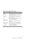
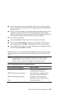
HSwitch. The model number of the H-switch is displayed. In this example
the model number is HPM40.
Type. The HPM40 is a 4-port H-switch.
Cables. In the example, H-switch ports 0 through 3 are enabled (P); H-
switch ports 4 through 7 are not present (–). Other indicators are V (valid),
* (present), and F (failed).
Temp. Displays the temperature inside the H-switch housing.
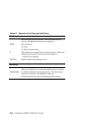
PCI Cab. This map shows the presence or absence of devices in each PCI
box in the system. Each PCI box has a maximum of four PCI hoses (two
hoses (0 and 1) on remote I/O riser 0 and two hoses (0 and 1) on remote I/O
riser 1.
In this example, PCI box 10 has a standard I/O module (S) in riser 0, hose
0, slot 1, and two low-powered devices (L) in riser 0, hose 1, slots 4 and 6.
A device is labeled according to its power usage: L is low-powered, M is
medium-powered, and H is high-powered.
Continuedonnextpage


