6-6 AlphaServer GS80/160/320 User’s Guide
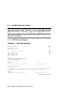
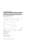
6.1.2 SRM Power-Up Display
Following the initial SCM power-up and the five test phases, the SRM
console takes control of the remaining portion of system power-up.
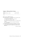
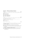
Example 6–2 SRM Power-Up Display
System Primary QBB0 : 0
System Primary CPU : 0 on QBB0
Par hrd/sft CPU Mem IOR3 IOR2 IOR1 IOR0 GP QBB Dir PS Temp
QBB# 3210 3210 (pci_box.rio) Mod BP Mod 321 (:C)
(-) 0/30 ---P PP --.- --.- Px.x P1.0 P P P PPP 26.5
(-) 1/31 -P-P PP --.- --.- --.- --.- P P P PPP 29.0
(-) 2/32 --P- --P- --.- --.- --.- --.- P P P PP- 25.0
(-) 3/33 ---P -P-- --.- --.- Px.x P0.0 P P P PP- 27.0
HSwitch Type Cables76543210 Temp(:C)
HPM40 4-port ----EEEE 29.0
PCI Rise1-1 Rise1-0 Rise0-1 Rise0-0 RIO PS Temp
Cab7654 321 7654 321 10 21 (:C)
10 ---- --- ---- --S -* P- 27.5
11 ---- --- --L- LMS -* PP 27.0
OpenVMS PALcode V1.75-1, Tru64 UNIX PALcode V1.68-1
system = QBB0123 +HS
QBB 0 = CPU 0 + Mem 0 1 + Dir + IOP + PCA 0 + GP (Hard QBB 0)
QBB 1 = CPU 0 2 + Mem 0 1 + Dir + IOP + PCA + GP (Hard QBB 1)
QBB 2 = CPU 1 + Mem 1 + Dir + IOP + PCA + GP (Hard QBB 2)
QBB 3 = CPU 0 + Mem 2 + Dir + IOP + PCA 0 + GP (Hard QBB 3)
shared RAM version is 1.3
hose 24 has a standard I/O module
starting console on CPU 0
initialized idle PCB
initializing semaphores
initializing heap
initial heap 2c0c0
memory low limit = 1f2000
heap = 2c0c0, 1ffc0
initializing driver structures
initializing idle process PID
initializing file system
initializing timer data structures
lowering IPL


