Removal and Replacement Procedures
Maintenance and Service Guide 5–65
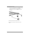
5.25 Serial Connector Module
1. Prepare the notebook for disassembly (Section 5.3)
and remove the following components:
a. Hard drive (Section 5.4)
b. MultiBay II device (Section 5.6)
c. Bluetooth board (Section 5.8)
d. Switch cover (Section 5.10)
e. Keyboard (Section 5.9)
f. Thermal plate (Section 5.12)
g. Heat sink (Section 5.13)
h. TouchPad (Section 5.17)
i. Display assembly (Section 5.19)
j. Top cover (Section 5.20)
k. System board (Section 5.22)
Serial Connector Module Spare Part Number Information
Serial connector module 382690-001


