


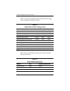

5–4 Maintenance and Service Guide
Removal and Replacement Procedures
Section Description
# of Screws Removed
5.9 Optical Drive 1 to remove the optical drive,
2 to remove the optical drive
bracket
5.10 Switch Cover 2
5.11 Keyboard 4
5.12 Display Assembly 6 to remove the display
assembly
6 to remove the display bezel
2 to remove the display hinge
base covers
4 to remove the display panel
2 to remove the display
release hook
4 to remove each display
hinge
1 to remove each wireless
antenna transceiver
5.13 Base Enclosure 18
5.14 Bluetooth Module 2
5.15 System Board 4
5.16 Display Release Button
Assembly
6
5.17 LED Board 2
5.18 Fan/Heat Sink Assembly 10
5.19 Processor 1 loosened
5.20 PC Card Assembly 2
5.21 ExpressCard Assembly 2
Disassembly Sequence Chart (Continued)