


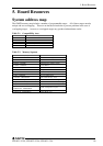

4. Jumper Setting
SPI-8451-LLVA, SPI-8452-LLVA, SPI-8451-LVA
35
4. Jumper Setting
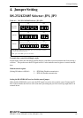
RS-232/422/485 Selector: JP1, JP3
Table 4.1. RS-232C/422/485 Selector (JP1, JP3)
RS-232C
RS-422
RS-485
1. For RS-485, TX+(pin 2) and RX+ (pin 3) must jumper together
inside the D type connector.
2. TX- (pin 1) and RX- (pin 4) is the same.
JP1 JP3
JP1 JP3
JP1 JP3
(Default)
9
7531
10
8642
19 17 15 13 11 9 7 5 3 123 21
20 18 16 14 12
10 8 6 4 225 22
19 17 15 13 11 9 7 5 3 123 21
20 18 16 14 12
10 8 6 4 225 22
19 17 15 13 11 9 7 5 3 123 21
20 18 16 14 12
10 8 6 4 225 22
97531
10
864
2
9
75
31
10
864
2
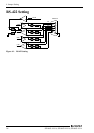
Transmit data control in half-duplex mode
In half-duplex mode, the transmission buffer must be controlled to prevent transmit data from causing a
collision. This product uses the RTS signal and bit 1 in the modem control register to control transmit
data.
Modem control register
(Setting I/O address +4H) bit 1: 0 … RTS High (Disables transmission)
1 … RTS low (Enables transmission)
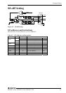
Setting the RS-422/RS-485 receiver disable control jumper
When the RS-422/RS-485 port is used, the RTS signal is used for driver enable control Connecting JP1
Pins 4 and 6 disables the receiver at the same time, preventing the port from receiving output data to an
external device.