


Title: Engineering Product Specification Telecom Circuit Protector Revision: L
Printed on: 7/14/2003 Sheet 8 of 18
This bulletin is intended to clearly present comprehensive product data and provide technical information that will help the end user with design
applications. Bussmann reserves the right, without notice, to change design or construction of any products and to discontinue or limit distribution of
any products. Bussmann also reserves the right to change or update, without notice, any technical information contained in this bulletin. Once a
product has been selected, it should be tested by the user in all possible applications.
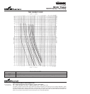
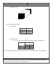
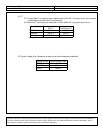
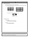
5.5 I
2
t
5.5.1 Typical Melt I
2
t is measured with a battery bank at 60V DC, 10x-rated current, time constant
of calibrated circuit less than 50 microseconds.
5.5.2 Maximum Total Clearing is measured on a 40A, 600V AC, unity power factor circuit.
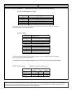
Catalog Symbol Typical Maximum
Melt I
2
t Total Clearing I
2
t
TCP500mA 1.3 A
2
s100 A
2
s
TCP1.25A 22.2 A
2
s100 A
2
s
TCP2A 30 A
2
s100 A
2
s
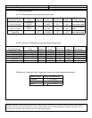
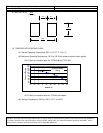
5.6 Typical Voltage Drop (Measured at rated current after temperature stabilizes)
Catalog Symbol Typical Voltage Drop
TCP500mA 471mV
TCP1.25A 205mV
TCP2A 205mV