


Title: Engineering Product Specification Telecom Circuit Protector Revision: L
Printed on: 7/14/2003 Sheet 17 of 18
This bulletin is intended to clearly present comprehensive product data and provide technical information that will help the end user with design
applications. Bussmann reserves the right, without notice, to change design or construction of any products and to discontinue or limit distribution of
any products. Bussmann also reserves the right to change or update, without notice, any technical information contained in this bulletin. Once a
product has been selected, it should be tested by the user in all possible applications.
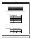
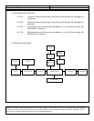
13.5 Thermal Shock Test:
MIL-STD-202, Method 107D, air-to-air except:
13.5.1 Samples are placed in a temperature chamber and subjected to 200 air-to-air cycles of the
following:
1) Hold -55°C+
2°C for 30+5 minutes
2) Transfer to 125°C+
2°C within 0.5 minutes
3) Hold 125°C±2°C for 30±5 minutes
4) Transfer to -55°C±2°C within 0.5 minutes
5) Repeat cycle 200 times
13.5.2 At completion of 200 cycles, resistance readings taken after temperature stabilization (25°C±5°C
for 15 minutes minimum to 24 hours maximum)
13.5.3 Samples divided into two equal lots of twenty
13.5.4 One set is tested to the non-destructive 100% current carry test. After completion, the samples
are subjected to the Time Current Characteristic Curve Generation.
13.5.5 The other set is subjected to the destructive Current Overload Test.
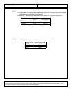
13.6 Maximum Current Carry Test
13.6.1 Performed after the non-destructive Load Humidity and 100% Current Carry Tests (same samples
used)
13.6.2 At the completion of the 100% Current Carry Test, the current is increased by 10% of the current
rating of the fuse. Increase occurs every 15 minutes until the fuse opens. Temperature is
monitored constantly.
13.7 Case Resistance Test
EIS/IS-722
13.8 Resistance to Dissolution of Metallization Test
ANSI J-STD-002, Test D
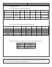
13.9 Mechanical Shock Test
MIL-STD-202, Method 213B, Test Condition A, except:
13.9.1 Test boards mounted to a shock test fixture, which in turn was mounted to the table of the shock
machine.
13.9.2 Shock machine calibrated for the required shock pulse.
13.9.3 Samples subjected to eighteen impacts, three impacts in each of the three mutually
perpendicular axis. Each shock pulse approximated a half-sine wave shape with a magnitude
of 50 g’s for 11±1 milliseconds.
13.9.4 High frequency vibration test is performed after the mechanical shock test is completed.
After the high-frequency vibration test, the samples undergo the 100% current carry test and the
Current overload tests.