


Description
• Surface Mount
• Environmentally rugged, complies with the EIA-IS-722
Standard
• Solder Immersion Compatible
• Targeted for Consumer Electronics
• Overcurrent protection of systems up to 125VAC/DC
• Wire-in-air design
Agency Information
• UL Listed Guide and File Numbers (250mA-12A):
JDYX & E195337
• UL Recognized Guide and File Numbers (15A):
JDYX2 & E195337
• CSA Component Acceptance: 053787 C 000 &
Class No: 1422 30
Environmental Data
• Shock: MIL-STD-202, Method 213, Test Condition 1
(100 G’s peak for 6 milliseconds)
• Vibration: MIL-STD-202, Method 201 (10-55 Hz, 0.06
inch, total excursion)
• Salt Spray: MIL-STD-202, Method 101, Test Condition
B (48 hrs)
• Insulation Resistance: MIL-STD-202, Method 302, Test
Condition A (After Opening) 10,000 ohms minimum
• Resistance to Solder Heat: MIL-STD-202, Method 210,
Test Condition F (20 sec, at 260° C)
• Thermal Shock: MIL-STD-202, Method 107, Test
Condition B (-65° C to +125° C)
Ordering
• Specify product code and packaging code
Soldering Method
• Wave Solder: 260°C, 10 sec max.
(MIL-STD-202, Method 210)
• Infrared Reflow: 260°C, 30 sec max.
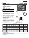
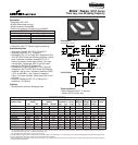
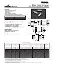
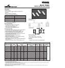
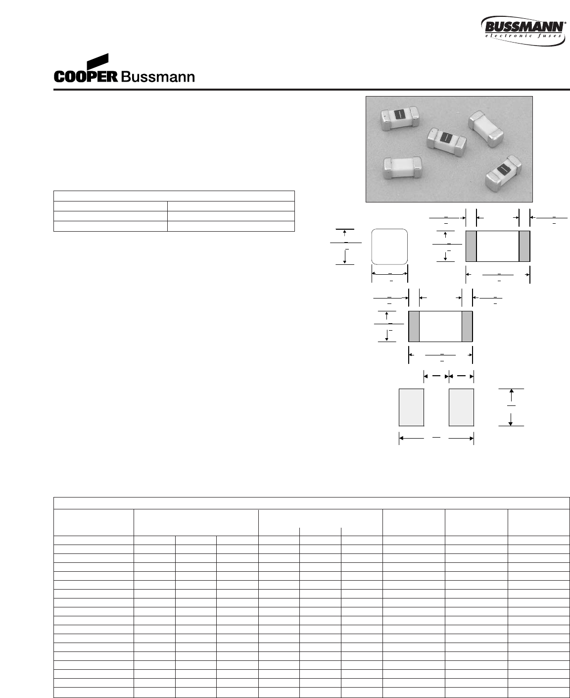
Brick
™
Fuses
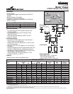
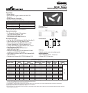
6125FA Series, Fast Acting
2.59+.250
(0.102+
.010)
2.59+
.250
(0.102+
.010)
2.6 3.0
(0.102) (0.118)
4.0
(0.157)
8.6
(0.339)
*AC Interrupting Rating (Measured at designated voltage, 100% power factor); DC Interrupting Rating (Measured at designated voltage, time constant of less than 50
microseconds, battery source)
** DC Cold Resistance (Measured at 10% of rated current)
†Typical Melting I
2
t (Measured with a battery bank at rated DC voltage, 10x-rated current, time constant of calibrated circuit less than 50 microseconds)
‡Typical Voltage Drop (Measured at rated current after temperature stabilizes)
Device designed to carry rated current for four hours minimum. An operating current of 80% or less of rated current is recommended, with further derating required at elevated
ambient temperatures.
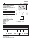
1.35+.25 1.35+.25
(0.053+
.010) (0.053+.010)
2.59+
.25
(0.102+
.010)
6.10+
.25
(0.240+
.010)
1.35+.25 1.35+.25
(0.053+
.010) (0.053+.010)
2.59+
.25
(0.102+
.010)
6.10+
.25
(0.240+
.010)
Land Pattern
Dimensions
mm
⁄(inches)
Drawing Not to Scale
Top View
Side View
End View
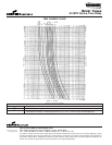
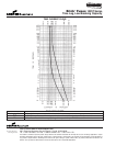
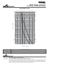
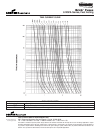
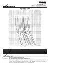
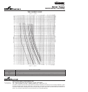
ELECTRICAL CHARACTERISTICS
% of Amp Rating Opening Time
100% 4 Hours Minimum
200% 5 Seconds Maximum
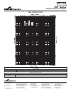
SPECIFICATIONS
Product Voltage Interrupting Resistance Typical Typical
Code Rating Rating* (ohms)** Melt Voltage
AC DC DC 125V AC 125V DC 86V DC Typ. I
2
t† Drop (V)‡
6125FA250mA 125V 125V 86V 50A 300A 10,000A 0.65 0.01 0.30
6125FA375mA 125V 125V 86V 50A 300A 10,000A 0.36 0.03 0.25
6125FA500mA 125V 125V 86V 50A 300A 10,000A 0.24 0.06 0.22
6125FA750mA 125V 125V 86V 50A 300A 10,000A 0.15 0.07 0.17
6125FA1A 125V 125V 86V 50A 300A 10,000A 0.11 0.14 0.17
6125FA1.25A 125V 125V 86V 50A 300A 10,000A 0.09 0.24 0.16
6125FA1.5A 125V 125V 86V 50A 300A 10,000A 0.07 0.41 0.15
6125FA2A 125V 125V 86V 50A 300A 10,000A 0.05 0.80 0.15
6125FA2.5A 125V 125V 86V 50A 300A 10,000A 0.038 1.4 0.14
6125FA3A 125V 125V 86V 50A 300A 10,000A 0.028 2.4 0.13
6125FA3.5A 125V 125V 86V 50A 300A 10,000A 0.025 3.3 0.13
6125FA4A 125V 125V 86V 50A 300A 10,000A 0.022 4.4 0.13
6125FA5A 125V 125V 86V 50A 300A 10,000A 0.016 7.8 0.12
6125FA6.3A 125V 125V 86V 50A 300A 10,000A 0.012 14.0 0.12
6125FA7A 125V 125V 86V 50A 300A 10,000A 0.011 19.0 0.114
6125FA10A 125V N/A 86V 50A N/A 10,000A 0.007 44 0.107
6125FA12A 125V N/A 86V 50A N/A 10,000A 0.006 69 0.103
6125FA15A N/A N/A 86V N/A N/A 10,000A 0.004 124 0.098