


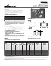
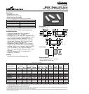
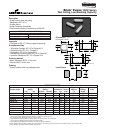
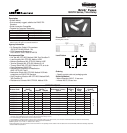
Description
• Designed to IEC 127-4
• Surface Mount fuse, time lag
• Solder Immersion Compatible
• Overcurrent protection of systems up to 250VAC
Approvals
• Designed to IEC 127, Sheet 4 (approval pending)
Environmental Data
•Termination Strength: IEC 127-4 Clause 8.3.2
• Soldered Joints: IEC 127-1 Clause 8.5
• Solderability: IEC 127-4 Clause 8.6.2 subjected to Test
Td of IEC-68-2-58 with the following conditions; Aging:
none. Immersion conditions: exceeds IEC 127-4.
Depth of immersion: entire metal surface. Flux type:
non-activated. Solder type: 60% tin and 40% lead
according to IEC 68-2-20, Appendix B.
• Resistance to Soldering Heat: IEC 127-4 Clause 8.7
subjected to Test Td of IEC 68-2-58 with the following
conditions; Aging: none. Immersion conditions: 260°C
± 5°C, 10 seconds ± 1 sec. Depth of immersion:
10mm. Flux type: activated. Solder type: 60% tin and
40% lead
• Insulation Resistance: IEC 127-4, Clause 9.3.3
(resistance ≥ 0.1Mohms)
Ordering
• Specify product code and packaging code
Soldering Method
• Wave Immersion: 260°C, 10 sec max.
• Infrared: 260°C, 30 sec max.
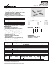
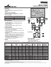
3.07 ± 0.15
(0.121 ± 0.006)
2.77 ± 0.15
3.07 ± 0.15
(0.109 ± 0.006)
(0.121 ± 0.006)
2.77 ± 0.15
(0.109 ± 0.006)
3.30
(0.130)
4.38
(0.172)
6.79
(0.267)
1.4 ± 0.25
1.4 ± 0.25
(0.055 ± 0.010)
(0.055 ± 0.010)
2.77 ± 0.15
(0.109 ± 0.006)
3.07 ± 0.15
(0.121 ± 0.006)
10.29 ± 0.20
(0.405 ± 0.008)
1.4 ± 0.25
1.4 ± 0.25
(0.055 ± 0.010)
(0.055 ± 0.010)
2.77 ± 0.15
(0.109 ± 0. 006)
3.07 ± 0.15
(0.121 ± 0.006)
10.29 ± 0.20
(0.405 ± 0.008)
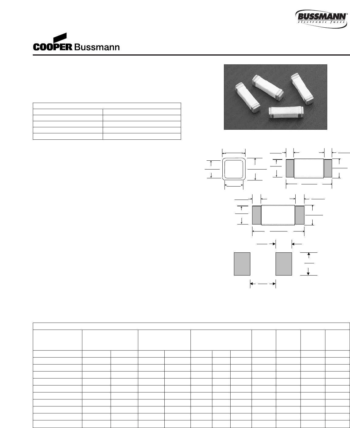
Land Pattern
Dimensions
mm
⁄(inches)
Drawing Not to Scale
Top View
Side View
End View
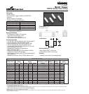
Brick
™
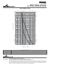
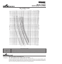
Fuses 1025T Series
Time Lag, Low Breaking Capacity
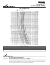
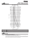
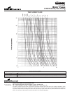
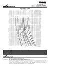
ELECTRICAL CHARACTERISTICS
% of Amp Rating Opening Time
125% 1 Hours Minimum
200% 2 Minutes Maximum
200% 1 Second Minimum
1000% 0.01 -- 0.1 Seconds
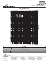
SPECIFICATIONS
Voltage Interrupting DC Cold Typical Typical Max. Marking
Product Code Rating Rating* Resistance** (ohms) Melting Voltage Voltage Code
AC DC 250VAC 125VDC min. typ. max. I
2
t† Drop‡ Drop‡
1025T250mA 250V 125V 100A 50A TBD TBD TBD TBD TBD 800 Dt
1025T500mA 250V 125V 100A 50A TBD TBD TBD TBD TBD 600 Ft
1025T800mA 250V 125V 100A 50A TBD TBD TBD TBD TBD 400 KKt
1025T1A 250V 125V 100A 50A TBD TBD TBD TBD TBD 300 Ht
1025T1.6A 250V 125V 100A 50A 0.064 0.074 0.083 12.26 155 mV 300 MMt
1025T2A 250V 125V 100A 50A TBD TBD TBD TBD TBD 300 Nt
1025T2.5A 250V 125V 100A 50A 0.045 0.048 0.051 32.91 TBD 300 Ot
1025T3.15A 250V 125V 100A 50A 0.030 0.034 0.038 54.98 184 mV 300 Qt
1025T4A 250V 125V 100A 50A TBD TBD TBD TBD TBD 300 St
1025T5A 250V 125V 100A 50A TBD TBD TBD TBD TBD 300 Tt
1025T6.3A 250V 125V 100A 50A TBD TBD TBD TBD TBD 300 OOt
*AC Interrupting Rating (Measured at designated voltage, greater than 95% power factor); DC Interrupting Rating (Measured at designated voltage, time constant of
the calibrated circuit is less than 1 millisecond, battery source)
** DC Cold Resistance (Measured at ≤10% of rated current)
†Typical Melting I
2
t (Measured with a battery bank at rated DC voltage, 10x-rated current, not to exceed IR, time constant of calibrated circuit less than 50 microseconds)
‡Typical Voltage Drop (Measured at rated current after temperature stabilizes)
• Device designed to carry rated current for four hours minimum. An operating current of 80% or less of rated current is recommended, with further derating required at
elevated ambient temperatures.