


Crestron CP2/CP2E 2-Series Integrated Control Processor
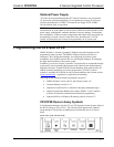
A voltage source is placed on Versiport 1 and <MinChange1> is set to 10
via an Analog Initialize symbol. The value of <i1> will not be propagated
until it changes by at least 10. If the current value is 500, then a new value
will not be reported until it changes to 510 or 490.
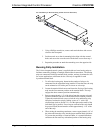
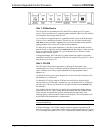
Slot 4: C2Y-RY8
The C2I-RY8 provides eight isolated relays for controlling low voltage contact
closure devices such as drapes, screens and lifts.
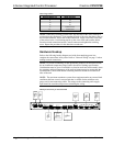
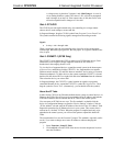
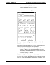
In Program Manager, drag the C2I-IO8 symbol from Program View to Detail View.
The symbol contains the following signals, arranged here according to mode:
Signals
• 8 relays: <A1> through <A8>
When a signal goes high, the corresponding relay closes for as long as the signal
remains high. When the signal goes low, the relay opens. If a signal is undefined, the
relay is open.
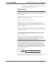
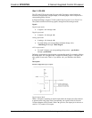
Slot 5: C2ENET-1 (CP2E Only)
The C2ENET-1 port enables the CP2E to control up to 252 Ethernet devices. Each
Ethernet device is assigned a unique identifier called an IP ID, which is a
hexadecimal value ranging from 03 to FE.
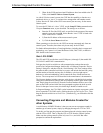
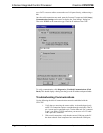
To view the list of supported devices, expand the control system in the bottom pane
of System Views and double-click the C2ENET-1 slot. Supported devices include
Ethernet control modules, PC and Web browser interfaces, and a variety of Crestron
Ethernet touchpanels. To add a device to the system expand the C2ENET-1 slot and
double-click the desired IP ID, or right-click and select Add Item from the submenu.
Then select the device you want to add.
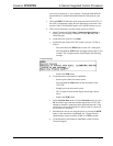
In Program Manager, the C2ENET-1 symbol contains no signals; to program a
controlled Ethernet device, expand the C2ENET-1 symbol in Program View. Then
drag the symbol to Detail View. (Alternatively, you can double-click the symbol.)
About the IP Table
In order for the CP2E (or any Ethernet-enabled control system) to control devices via
Ethernet, the IP ID of the device must be associated with an IP address, and both the
IP ID and IP address must be entered into the IP Table of the control system.
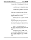
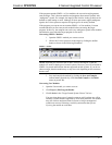
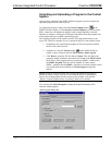
You can create an IP Table in two ways. The first method is to double-click the
device in Configuration Manager to open the “Device Settings” window. Click the
“IP Net Address” tab and enter the IP address of the device in the “IP Address” field.
Repeat this procedure for all Ethernet devices in your system. This creates what is
referred to as a “default” IP Table. When the program is compiled and ready to be
uploaded to the control system, you will have the option to upload this default IP
Table.
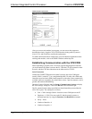
The second method is to use the Crestron Viewport. This method is especially useful
on site, if you want to change one or more IP addresses without changing the
program.
1. Select Functions | Setup IP Table.
2. Click Add and select the IP ID of the device from the drop-down list, then
enter the IP address.
Operations Guide - DOC. 5980 2-Series Integrated Control Processor: CP2/CP2E• 17