


2-Series Integrated Control Processor Crestron CP2/CP2E
Module Header Information
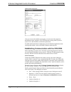
After you convert each module in a program, you can convert the program as
described previously: drag the CP2 or CP2E onto the existing control system in
System Views and click Yes to confirm the replacement.
For further information about compile-time errors and detailed explanations about
working with modules, refer to the SIMPL Windows online help file.
Establishing Communication with the CP2/CP2E
Before uploading a program to the CP2/CP2E or performing diagnostic functions,
you must connect the control system to the PC. With the CP2, this connection must
be serial; with the CP2E the connection can be either serial or TCP/IP.
Serial Connection
Connect the COMPUTER port on the control system to one of the COM ports
(usually COM 1) on the PC. Use a straight-through RS-232 cable with a DB9 male
connector on one end and a DB9 female connector on the other. Most commercially
available cables are acceptable; they should have at least 5 pins for transmit, receive,
ground, and hardware handshaking.
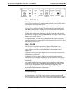
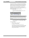
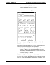
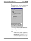
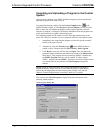
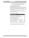
Open the Crestron Viewport and click Setup | Communication Settings to display
the “Port Settings” dialog box. Then click RS-232 as the connection type.
The PC communication settings specified here should match the protocol that the
CP2/CP2E expects. The settings are as follows:
• Port = COM 1 through COM 8. Select the correct COM port on the PC.
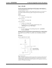
• Baud rate = 115200 (You can set the PC and the control system to a
different baud rate, by using the Functions | Set Baud Rate command.
• Parity = None.
• Number of data bits = 8.
• Number of stop bits = 1.
20 • 2-Series Integrated Control Processor: CP2/CP2E Operations Guide - DOC. 5980