


Crestron CP2/CP2E 2-Series Integrated Control Processor
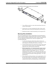
NOTE: The orientation of this connector is “upside down” compared to other
Crestron network devices (e.g., CNX-BIPAD8, CNX-RMCLV). Be sure the mating
Cresnet cable connector is properly aligned before attempting to insert it, to avoid
damage to the CP2/CP2E unit.
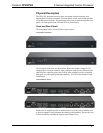
This connector (typical Crestron network port labeled G Z Y 24) is used for
expansion to Cresnet and SmarTouch peripherals. This connector can also serve as a
24W power source to the network when CP2/CP2E unit power is supplied through
the 24VDC power supply connector by an optional AC power pack (purchased
separately); otherwise, power to the unit is supplied through this connector. There is
a 24W maximum load rating for power output. Refer to “Network Wiring” on page
11 for details.
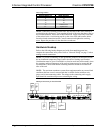
COM (A – C)
COM C
COM B
COM A
These three DB9 (male) software programmable, bi-directional serial ports are
available for RS-232, RS-422, or RS-485 communication, with hardware and
software handshaking. Speeds are rated up to 115,200 bps. All three ports are
Cresnet Accelerator ready. The Cresnet Poll Accelerator effectively increases the
network speed, fan-out, and device addresses by a factor of 8 for each Poll
Accelerator added to the system.
NOTE: The pinout of each 9-pin port is non-standard (refer to the table after these
notes, titled "Non-Standard COM Pinout"); it contains RS-422 pins in addition to
RS-232. This may result in a conflict with some equipment and therefore all nine
pins should not be used. Only the required pins for each communication type should
be connected. For RS-232 and –422, pins 2, 3, 5, 7, and 8 are wired straight through.
NOTE: Data Set Ready (DSR) and Data Terminal Ready (DTR) are not supported.
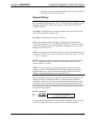
NOTE: To support RS-485, tie pin 1 (RXD-) to pin 9 (TXD-) and pin 4 (TXD+) to
pin 6 (RXD+) in the cable (refer to the table after this note, titled "COM Pinout to
RS-485 Bus".
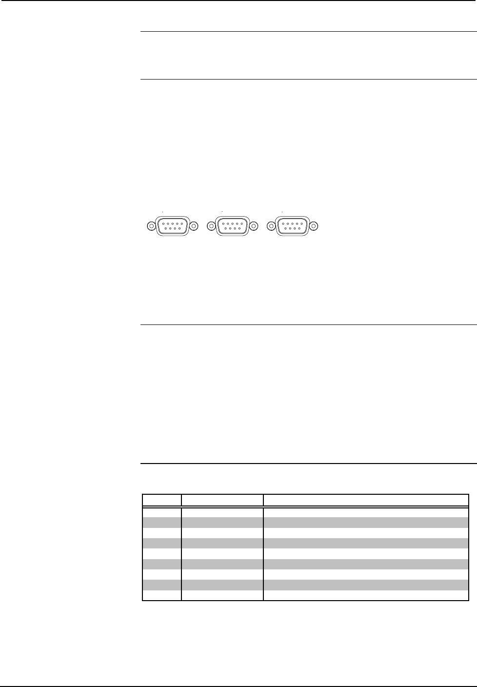
Non-Standard COM Pinout
PIN DIRECTION DESCRIPTION
1* To CP2/CP2E (RXD-) RS-422 Receive Data (Idles low)
2 To CP2/CP2E (RXD) RS-232 Received Data
3 From CP2/CP2E (TXD) RS-232 Transmitted Data
4 From CP2/CP2E (TXD+) RS-422 Transmit Data (Idles high)
5 RS-232 and RS-422 Signal Common
6 To CP2/CP2E (RXD+) RS-422 Receive Data (Idles high)
7 From CP2/CP2E (RTS) RS-232 Request to Send
8 To CP2/CP2E (CTS) RS-232 Clear to Send
9 From CP2/CP2E (TXD-) RS-422 Transmit Data (Idles low)
Where: *= RS-422 transmit and receive are balanced signals requiring two lines plus a ground in each
direction. RXD+ and TXD+ should idle high (going low at start of data transmission). RXD-
and TXD- should idle low (going high at start of data transmission). If necessary, RXD+/RXD-
and TXD+/TXD- may be swapped to maintain correct signal levels.
Operations Guide - DOC. 5980 2-Series Integrated Control Processor: CP2/CP2E• 5