5-Port Power over Ethernet Switch Crestron CEN-SW-POE-5
Connectors & Indicators (Continued)
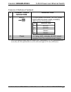
# CONNECTORS &
INDICATORS
DESCRIPTION
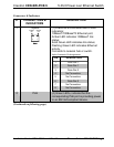
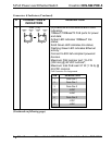
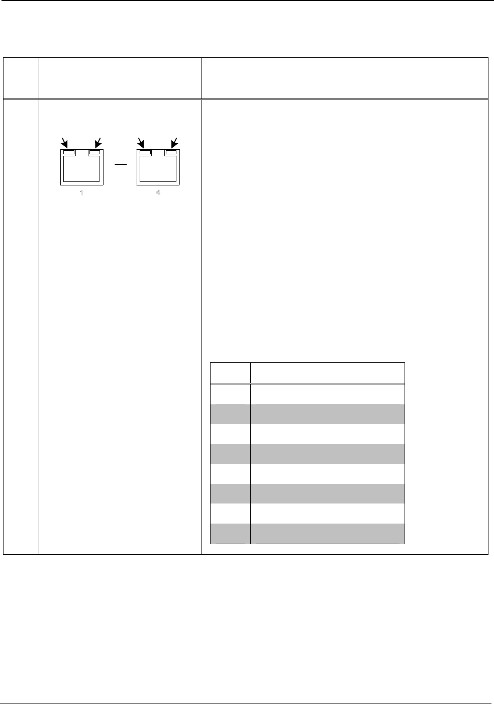
3 PoE (1-4)
AMBER
LED
GREEN
LED
AMBER
LED
GREEN
LED
8 1
8 1
(4) 8-wire RJ-45 connectors with 2 LED
indicators;
10BaseT/100BaseTX PoE ports for power
and data;
Amber LED indicates 100BaseT link
status;
Solid Green LED indicates link status;
Flashing Green LED indicates Ethernet
activity.
Connect to 802.3af-compliant powered
devices.
Maximum PoE load per port: 15.4 W
(350 mA) @ 48 VDC nominal*;
Maximum total PoE load: 57 W (1.19 A) @
48 VDC nominal.
PoE Connector Pin Assignments
PIN DESCRIPTION
1 Data Pair 1
2 Data Pair 1
3 Data Pair 2
4 +VDC
5 +VDC
6 Data Pair 2
7 -VDC
8 -VDC
(Continued on following page)
8 • 5-Port Power over Ethernet Switch: CEN-SW-POE-5 Installation Guide – DOC. 6694A


