


Crestron CP2/CP2E 2-Series Integrated Control Processor
Slot 3: C2I-IO8
The CP2 and CP2E provide eight I/O ports called Versiports, each of which can
function as a digital input, a digital output, or an analog input. Each Versiport has a
corresponding pullup resistor.
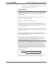
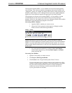
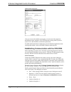
In Program Manager, drag the C2I-IO8 symbol from Program View to Detail View.
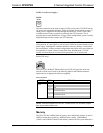
The symbol contains the following signals, arranged here according to mode:
Signals
Digital output mode
• 8 digitals: <o1> through <o8>
Digital input mode
• 8 digitals: <i1> through <i8>
Analog input mode
• 8 analogs: <i1> through <i8>
• For each analog, one corresponding minimum change value:
<MinChange1> through <MinChange8>
All Versiport modes
• For each Versiport, one corresponding pullup resistor: <pu-disable1>
through <pu-disable8>
Defining a signal puts the signal into the corresponding mode. For example, defining
the analog input <i1> configures that Versiport as an analog input. A Versiport can
only operate in one mode. That is, if you define <o1> you should not also define
<i1>.
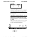
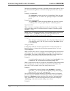
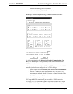
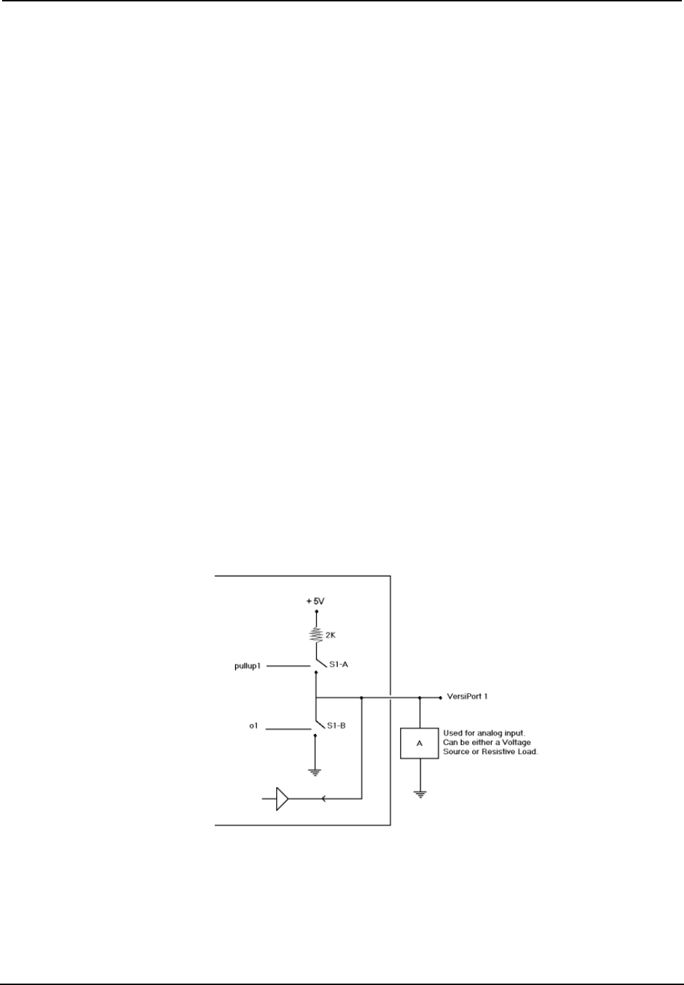
Description
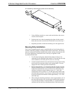
Internal configuration of a Versiport
Digital Output Mode
When a Versiport is operating in digital output mode, the output pin will be shorted
to ground on the rising edge of the corresponding <o> signal (switch S1-B in the
Versiport diagram will be closed). When <o> goes low, the output pin is driven to a
value of +5V (switch S1-B is open).
Operations Guide - DOC. 5980 2-Series Integrated Control Processor: CP2/CP2E• 15