


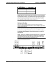

2-Series Integrated Control Processor Crestron CP2/CP2E
Driving the corresponding <pu-disable> signal high can modify this behavior. This is
not recommended, though, since it will cause the output pin to float when <o> goes
low.
Example 1 (recommended):
The <pu-disable1> signal is driven low or left undefined. When <o1> goes
low, Versiport 1 is at +5V. When <o1> goes high, Versiport 1 is shorted to
ground.
Example 2 (not recommended):
The <pu-disable1> signal is driven high. When <o1> goes low, Versiport
1 is floating. When <o1> goes high, Versiport 1 is shorted to ground.
Digital Input Mode
When a Versiport is operating in digital input mode, the corresponding <i> signal
will go high whenever the C2I-IO8 detects that the Versiport is shorted to ground
(threshold < +2.5V).
NOTE: Here, as with digital output mode, the corresponding pullup resistor should
be enabled. That is, <pu-disable> should be given the signal name 0 or left
undefined; otherwise the input will always read as logic low.
Example 3:
When Versiport 3 is shorted to ground, <i3> will go high. When Versiport 3
is not shorted to ground, <i3> will go low (so long as <pu-disable> equals
0 or is undefined).
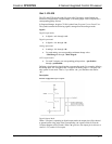
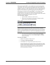
Analog Input Mode
In analog input mode, the Versiport is typically tied to a resistive load (such as a
humidity sensor) or a voltage source (both can be represented by box "A" in the
Versiport diagram).
When a resistive load is tied to a Versiport, the corresponding pullup resistor must be
enabled (again, this means that <pu-disable> should be given the signal name 0 or
left undefined). This creates a voltage divider and provides a varying voltage level,
based on the current resistance of the sensor for the C2I-IO8 to read.
Example 4:
A resistive humidity sensor is tied to Versiport 1 (and <pu-disable1> is low
or undefined). <i1> will assume the corresponding analog value.
When a voltage source is tied to a Versiport, the corresponding pullup resistor should
be disabled (the only case where the default setting should be overridden). This
allows the C2I-IO8 to read the value of the voltage source directly.
Example 5:
A voltage source is tied to Versiport 1 and <pu-disable1> is given the
signal name 1. <i1> will assume the corresponding analog value (ranging
from 0 to 65535, or 0 to +10V on the input pin).
The C2I-IO8 does not propagate all changes in the analog values of its Versiports,
since this can lead to undesirable results if the input source is not clean or has jitter.
Rather, the <MinChange> signals should be used to specify a "minimum change"
value, such that the C2I-IO8 will not propagate the new value until it changes by
<MinChange>. (The default minimum change value is 2048.)
Example 6:
16 • 2-Series Integrated Control Processor: CP2/CP2E Operations Guide - DOC. 5980