


Crestron CP2/CP2E 2-Series Integrated Control Processor
some may be internal (e.g., for a modem). Consult the manufacturer’s
documentation for further information about the COM ports on your
PC.
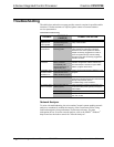
3. Check the ERR LED indicator on the front panel of the CP2/CP2E. If
this LED is illuminated, unplug the unit and reapply power after a few
seconds. If the LED illuminates again, call Crestron customer service.
4. With a serial connection, reset the control system as follows:
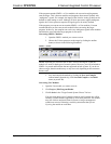
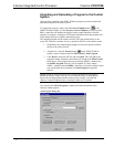
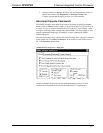
a. Open Viewport and click Setup | Communications Settings to
display the “Port Settings” dialog box. Choose RS-232 as the
connection type.
b. Set the baud rate of the PC to 115200.
c. Set the baud rate of the CP2/CP2E control system to 115200, as
follows:
- Press and release the HWR button on the unit’s front panel.
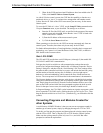
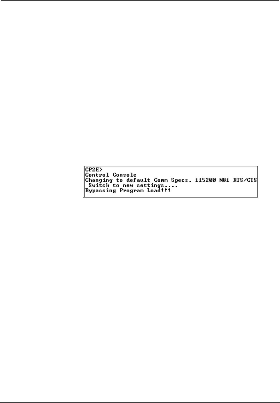
- Press and hold the SWR button for approximately three to five
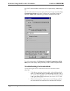
seconds. The Viewport console should display the following
message:
Viewport Message
- Release the SWR button.
d. If communication still cannot be established:
- Remove power from the control system.
- Press and hold the SWR button on the front panel of the
CP2/CP2E.
- Reapply power to the control system.
- The Viewport console should display the message shown
above.
- Release the SWR button.
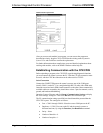
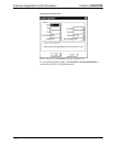
e. Select Set Baud Rate on the Viewport Functions menu (or press
F8) and choose any baud rate from the drop-down list. This will
attempt to establish a connection at the indicated baud rate. If the
connection is successful, both the PC and the control system will
be set to the new baud rate.
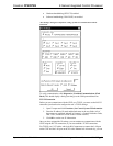
f. Reinitialize the unit by recycling the power or pressing the HWR
button. If the connection is established, the Viewport console
should display some text and the <CP2> or <CP2E> prompt.
g. If communication still cannot be established, contact Crestron
Customer Support.
Operations Guide - DOC. 5980 2-Series Integrated Control Processor: CP2/CP2E• 23