


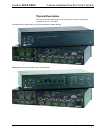

Crestron AV2 & PRO2 2-Series Integrated Dual Bus Control System
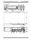
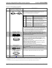
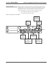
Connectors, Controls & Indicators
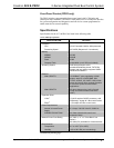
#
CONNECTORS
1
,
CONTROLS & INDICATORS
DESCRIPTION
1
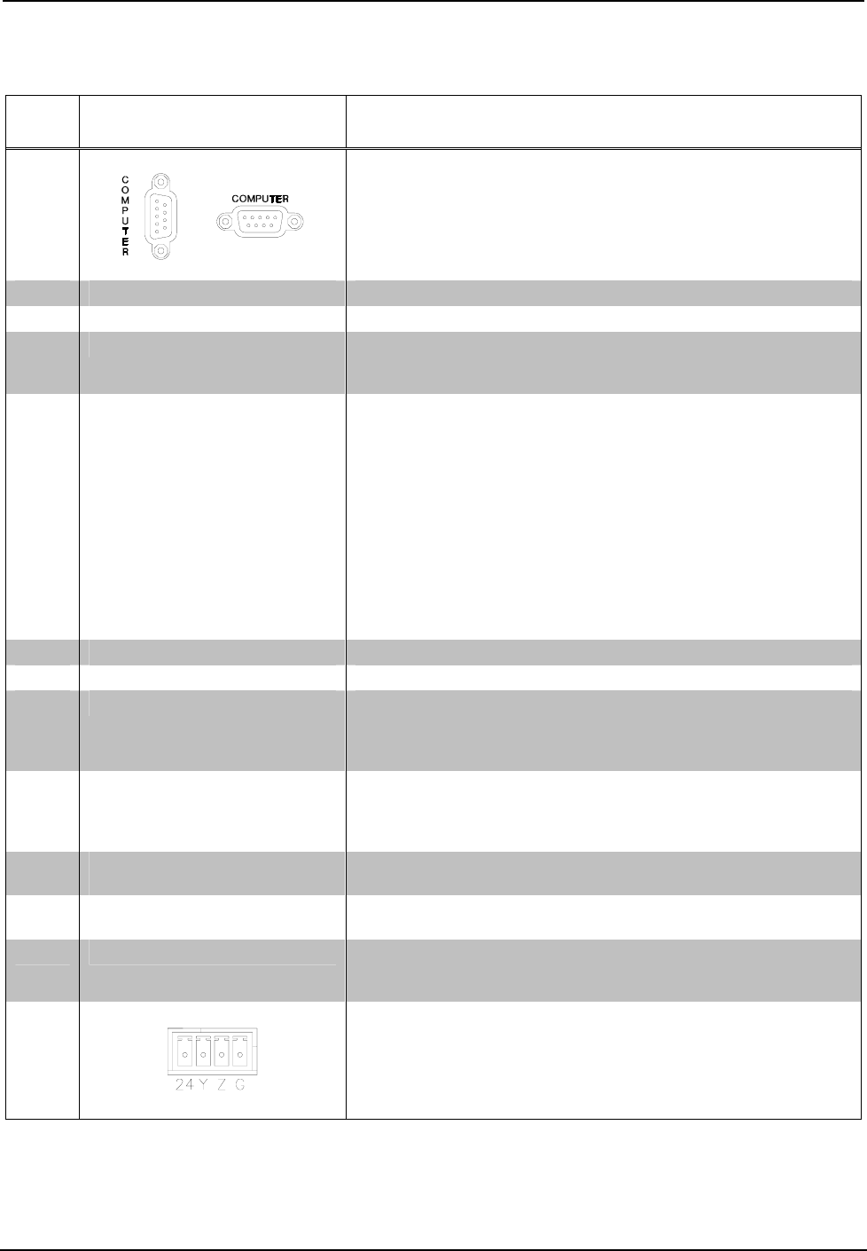
COMPUTER
FRONT PANEL REAR PANEL
DB9F connectors (one on front panel and one on rear) are used
when programming with a PC. Each port is modem compatible.
(Modem and PC cables not included.)
2 PWR LED Indicates 24 Volts DC power supplied from Cresnet control network.
3 NET LED Indicates communication with Cresnet System.
4 MSG LED
2
Illuminates when a message is detected. To decipher content,
examine the message available from the menu function buttons or
through the Crestron Toolbox™.
5 COM (A – F) LEDS
3
RXD - Illuminate during reception of data from serial devices
attached to the respective COM ports.
TXD – Illuminate during transmission of data to serial devices
attached to the respective COM ports.
RTS – Illuminate to reflect state of the RTS pin on the respective
COM port. If no handshaking is specified, the RTS line will be high
and the associated LED is also high. When RTS flow control is
enabled, RTS indicates the unit is ready to receive data from serial
devices attached to the respective COM ports.
CTS – Illuminate to reflect state of the CTS pin on the respective
COM port. An illuminated LED means the CTS line is high. When
CTS flow control is enabled, CTS indicates the serial devices on the
respective COM ports are ready to accept data.
6 IR – SERIAL (A – H) LEDS
3
Indicate activity on the respective IR-SERIAL lines.
7 RELAY (1 – 8) LEDS
3
Indicate the respective relay is closed.
8 RESET BUTTONS
HW-R - Initiates system hardware reset.
SR-R - Pressing this in combination with HW-R button performs a
system restart without loading the program. Pressing it alone
momentarily while the system is running restarts the program.
9 LAN (A – B) LEDS
4
LNK – Indicate the Ethernet card has established a valid Ethernet
connection.
ACT – Indicate communication (activity) at the respective port on the
Ethernet card.
10
LCD SCREEN & MENU
BUTTONS
3
Permits local control; refer to “Operation” on page 18 for details.
11
INPUT – OUTPUT
(1 – 8) LEDS
3
Indicate when input voltage thresholds for the respective I/O ports
are exceeded or when the output is active.
12 SLOT (1 – 3) LEDS
3
Indicate an expansion card is inserted into the respective slot.
These LEDS turn off momentarily when data is sent to the card or
received from the card.
13
NET
Four-position terminal block connector for data and power.
Connects to Cresnet control network.
Pin 1 (24) Power
Pin 2 (Y) Data
Pin 3 (Z) Data
Pin 4 (G) Ground
(Continued on following page)
Operations Guide – DOC. 5957B 2-Series Integrated Dual Bus Control System: AV2 & PRO2 • 7