


Crestron AV2 & PRO2 2-Series Integrated Dual Bus Control System
Connect the Device
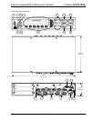
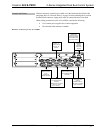
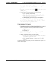
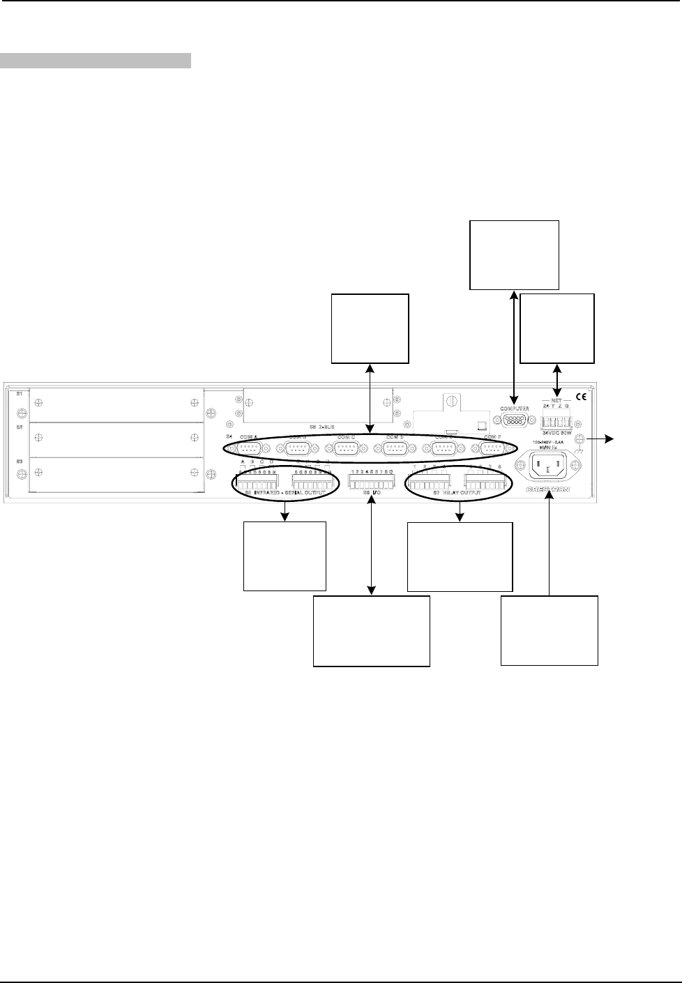
Make the necessary connections as called out in the illustration that follows this
paragraph. Refer to “Network Wiring” on page 10 before attaching the 4-position
terminal block connector. Apply power after all connections have been made.
When making connections to the AV2 & PRO2, consider the following:
• Use Crestron power supplies for Crestron equipment.
• The included cable cannot be extended.
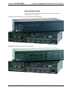
Hardware Connections for the AV2 & PRO2
COM (A - F):
TO ANY RS-232,
-422 OR -485
DEVICE
COMPUTER:
TO SERIAL PORT
ON PC (ANOTHER
DB9 CONNECTOR
ON FRONT PANEL)
CRESNET:
TO ANY
CRESNET
NETWORK
DEVICE
GROUND
INFRARED-
SERIAL OUTPUT
(A - H):
TO IRP2 OR
SERIAL DEVICES
RELAY OUTPUT (1 - 8):
TO CONTROLLABLE
DEVICES
100 - 240V ~2.4A
50/60 Hz
(POWER SUPPLY):
TO OUTLET (POWER
CORD SUPPLIED)
FROM DEVICE OUTPUTS
- CONTACT CLOSURES
- RELAY CLOSURES
I/O (1 - 8):
TO CONTROLLABLE
DEVICES
Operations Guide – DOC. 5957B 2-Series Integrated Dual Bus Control System: AV2 & PRO2 • 13