


2-Series Integrated Dual Bus Control System Crestron AV2 & PRO2
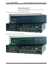
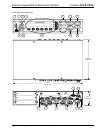
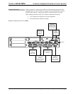
Connectors, Controls & Indicators (Continued)
#
CONNECTORS
1
,
CONTROLS & INDICATORS
DESCRIPTION
14
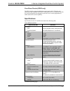
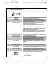
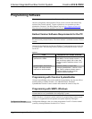
COM (A – F)
5, 6, 7
COM F
COM A
(6) DB9 male, bidirectional RS-232/422/485 ports. Up to 115.2k
baud, hardware and software handshaking support. Ports C-F
support C2N-NPA8 Network Poll Accelerator
8
.
PIN DIRECTION DESCRIPTION
1*
To AV2 or PRO2
(RXD-) RS-422 Receive Data (Idles low)
2
To AV2 or PRO2
(RXD) RS-232 Received Data
3
From AV2 or PRO2
(TXD) RS-232 Transmitted Data
4
From AV2 or PRO2
(TXD+) RS-422 Transmit Data (Idles high)
5
RS-232 and RS-422 Signal Common
6
To AV2 or PRO2
(RXD+) RS-422 Receive Data (Idles high)
7
From AV2 or PRO2
(RTS) RS-232 Request to Send
8
To AV2 or PRO2
(CTS) RS-232 Clear to Send
9
From AV2 or PRO2
(TXD-) RS-422 Transmit Data (Idles low)
* RS-422 transmit and receive are balanced signals requiring two lines
plus a ground in each direction. RXD+ and TXD+ should idle high (going
low at start of data transmission). RXD- and TXD- should idle low (going
high at start of data transmission). If necessary, RXD+/RXD- and
TXD+/TXD- may be swapped to maintain correct signal levels.
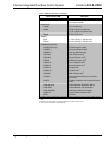
15
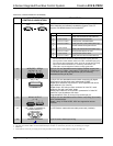
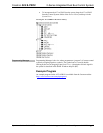
INFRARED - SERIAL
OUTPUT (A – H)
9
A B C D
E F G H
S G S G S G S G
INFRARED - SERIAL OUTPUT
S G S G S G S G
(8) 2-pin 3.5 mm detachable terminal blocks IR/Serial output ports.
IR output up to 1.2 MHz; 1-way serial TTL/RS-232 (0-5 Volts) up to
115.2k baud. Individual signal generator per port, allowing
simultaneous firing of all ports.
16
I/O (1 – 8)
10
S6 I/O
12345678G
(1) 9-pin 3.5 mm detachable terminal block comprising (8) digital
input/output or analog input ports (referenced to GND);
Digital Input: Rated for 0-24 Volts DC, input impedance 20k ohms,
logic threshold 1.24 Volts DC;
Digital Output; 250 mA sync from maximum 24 Volts DC, catch
diodes for use with “real world” loads;
Analog Input: Rated for 0-10 Volts DC, protected to 24 Volts DC
maximum, input impedance 20k ohms;
Programmable 5 Volts, 2k ohms pull-up resistor per pin.
17
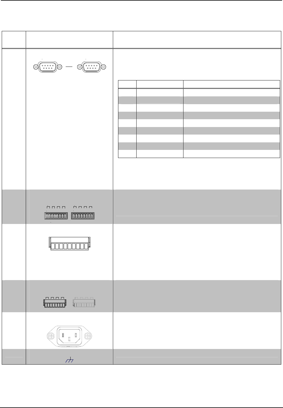
RELAY OUTPUT
(1 – 8)
RELAYS7
1234
OUTPUT
5
678
(2) 8-pin 3.5 mm detachable terminal blocks comprising (8) normally
open, isolated relays;
Rated 1 Amp, 30 Volts AC/DC, MOV arc suppression across
contacts.
18
100 – 240V ~2.4A 50/60 Hz
(POWER SUPPLY)
(1) IEC Socket, mates with removable power cord (included).
19
CHASSIS GROUND
(1) 6-32 screw, chassis ground lug.
1. Interface connectors for NET, Infrared-Serial, I/O and Relay Output ports are provided with the unit.
2. This LED was labeled “ERR” on units manufactured prior to 2005. It is functionally the same; only the labeling has changed.
3. PRO2 only.
4. LAN LEDs are active only if a single port or dual port Ethernet card (which is field installed) occupies the Z-Bus slot.
8 • 2-Series Integrated Dual Bus Control System: AV2 & PRO2 Operations Guide – DOC. 5957B