


Ethernet OEM Module Crestron eServer™
device, a unique IP address, subnet mask, default router, and IP table settings must
be defined. These settings among others can be defined using setup menus. A future
release of the Crestron Viewport will provide integrated tool support.
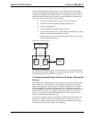
The eServer setup menus can be accessed only after connecting the communications
port of the PC to the COM IN port on the eServer. A serial cable is provided in the
dealer kit. After connecting the eServer and before applying power to it, open the
communications package that resides on the PC. Viewport from either SIMPL
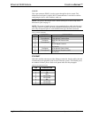
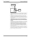
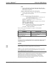
Windows or VisionTools Pro-e is used in the illustrations that follow. Be sure to set
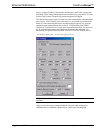
the PC communication parameters (Alt+D) as shown after this paragraph. No
handshaking is required (do not check the XON/XOFF or RTS/CTS check boxes).
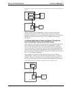
“Port Settings” Dialog Box – as viewed after entering Alt+D
NOTE: If XON/XOFF is checked, communication with the device may be
unreliable.
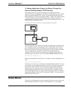
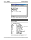
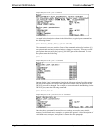
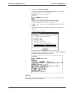
Apply power to the eServer and notice that the Viewport window changes as
communication is established with the eServer, shown after this paragraph.
12 • Ethernet OEM Module: eServer™ Operations Guide - DOC. 8148