


iMedia Wall Plate Computer & Video Center Crestron IM-WCCV-M
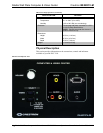
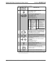
Connectors, Controls & Indicators (Continued)
# CONNECTORS,
CONTROLS &
INDICATORS
DESCRIPTION
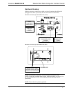
2
VIDEO
(1) RCA female, composite video input;
Input impedance: 75 Ω;
Maximum input: 1 V
p-p
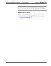
3
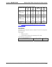
PC
PIN 1
PIN 6
PIN 15
(1) DB15HD female, RGB (VGA) input:
Formats: RGBHV, RGBS, RG
s
B;
Input impedance: 75 Ω;
Sync impedance: 1 kΩ;
Maximum input level: 1 V
p-p;
Maximum sync level: 5 V
p-p
PIN FUNCTION PIN FUNCTION
1 Red Video 9 No Connect
2 Green Video 10 Ground
3 Blue Video 11 No Connect
4 Reserved 12 Monitor Sense 1
5 Ground 13 Horizontal Sync
6 Red Ground 14 Vertical Sync
7 Green
Ground
15 Monitor Sense 2
8 Blue Ground
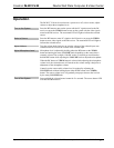
4
VIDEO
(1) Pushbutton with green LED; Momentary press
initiates “system power on” command and selects
local VIDEO input; press and hold for five seconds
or more initiates “system power off”.
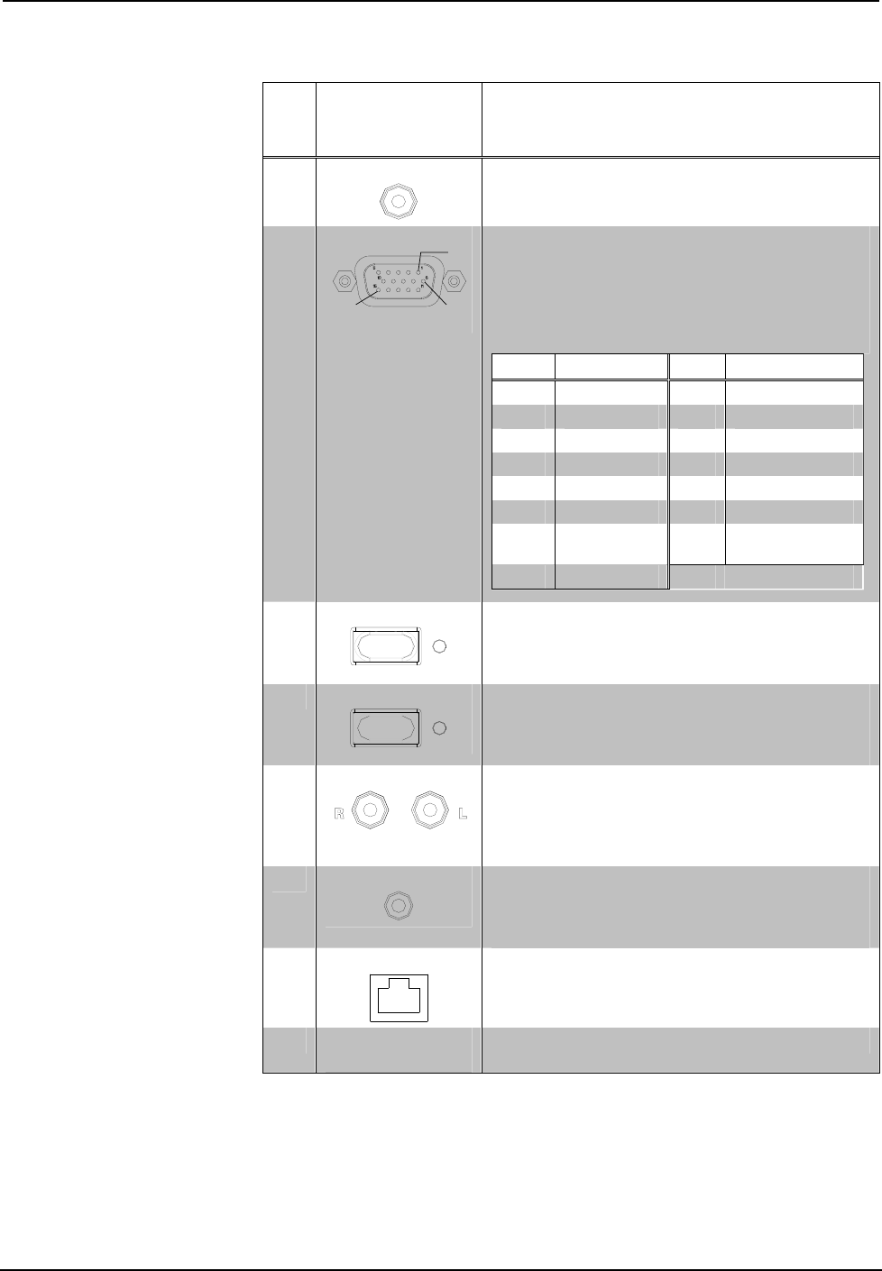
5
PC
(1) Pushbutton with green LED; Momentary press
initiates “system power on” command and selects
local PC input; press and hold for five seconds or
more initiates “system power off”.
6
AUDIO
(2) RCA female;
Unbalanced stereo line level audio input (linked
with VIDEO);
Maximum input level: 2 V
rms
;
Input impedance: 10 kΩ
7
AUDIO
(1) 3.5 mm TRS mini phone jack;
Unbalanced stereo line level audio input;
Maximum input level: 2 V
rms
;
Input impedance: 10 kΩ
8
IM
1, 2, 3
1
8
(1) 8-wire RJ-45 female, iMedia output port;
Connects to IM input port of an iMedia receiver via
CresCAT-IM cable.
9
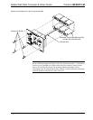
GROUNDING
WIRE
(1) flying lead, green, chassis ground wire
4
.
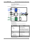
1. The eight-pin RJ-45 iMedia port accepts CresCAT-IM or CAT5E/CAT6 carrying video, audio, power
and control signals. Refer to the table on the following page for connector pinouts. Power is supplied
to pins 4 and 5 from the IM receivers.
6 • iMedia Wall Plate Computer & Video Center: IM-WCCV-M Operations & Installation Guide – DOC. 6621A