IPAC
Introduction
This document contains instructions for installing the IPAC series of wall-mounted,
Integrated Professional Automation Computers.
The IPAC is designed for installation in a standard 3-gang electrical box.
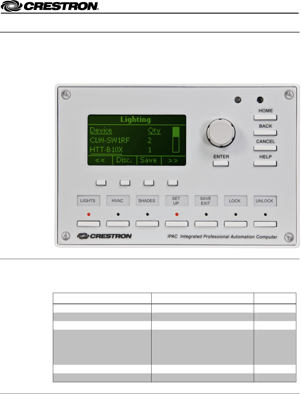
IPAC-GL1-W-T Physical View (shown in white)
Supplied Parts
The parts supplied with the IPAC are listed in the following table.
Supplied Hardware for the IPAC
DESCRIPTION PART NUMBER QUANTITY
Mounting Plate with Ground Wire 4506280 1
Screws, 06-32 x ¾”, Combo Head 2009211 4
Screws, 04-40 x ¼”, Pan, Phil 2007156 2
Screws, 04-40, 7/16", Pan, Phil, Blk
(for Black units)
OR
Screws, 04-40, 7/16", Pan, Phil, Zinc
(for White units)
2022900
2013409
4
Label Sheet
4505784 (Black) OR 4506570 (White)
1
Front Cover
4505711 (Black) OR 4505867 (White)
1
Crestron Electronics, Inc. Installation Guide – DOC. 6696A
15 Volvo Drive Rockleigh, NJ 07647 (2022187)
Tel: 888.CRESTRON 12.08
Fax: 201.767.7576 Specifications subject to
www.crestron.com change without notice.


