


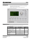
Integrated Professional Automation Computer Crestron IPAC
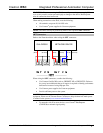
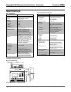
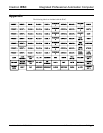
LAN Connector
The following illustration shows the pin assignments of the RJ-45 LAN connector.
WARNING: Incorrect wiring may damage the IPAC.
GREEN
LED
YELLOW
LED
PIN 8
PIN 1
PIN SIGNAL PIN SIGNAL
1 TX + 5 N/C
2 TX - 6 RC -
3 RC+ 7 N/C
4 N/C 8 N/C
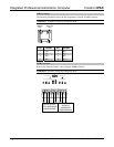
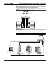
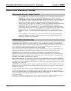
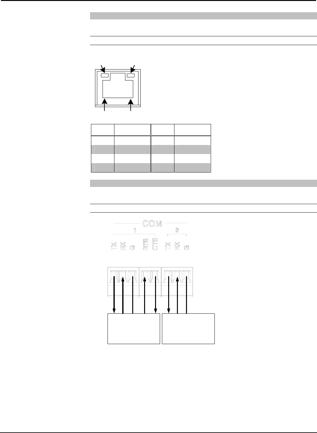
COM Connector
Refer to the illustration below when wiring the COM connector.
WARNING: Incorrect wiring may damage the IPAC.
RS-232 DEVICE
WITH HARDWARE
HANDSHAKING
RX TX G CTS RTS
RS-232 DEVICE
WITHOUT
HARDWARE
HANDSHAKING
RX TX G
4 • Integrated Professional Automation Computer: IPAC Installation Guide – DOC. 6696A