Document Number: 38-07138 Rev. *B Page 4 of 19
Test Mode
The TEST input is a three level input. In normal system
operation, this pin is connected to ground, enabling the
CY7B991 or CY7B992 to operate as explained in “Skew Select
Matrix” on page 3. For testing purposes, any of the three level
inputs can have a removable jumper to ground, or be tied LOW
through a 100Ω resistor. This enables an external tester to
change the state of these pins.
If the TEST input is forced to its MID or HIGH state, the device
operates with its internal phase locked loop disconnected, and
input levels supplied to REF directly controls all outputs. Relative
output to output functions are the same as in normal mode.
In contrast with normal operation (TEST tied LOW), all outputs
function based only on the connection of their own function
selects inputs (xF0 and xF1) and the waveform characteristics of
the REF input.
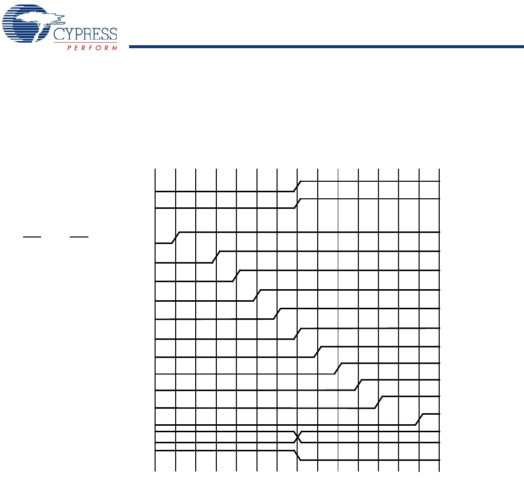
Figure 1 shows the typical outputs with FB connected to a zero skew output.
[4]
Figure 1. Typical Outputs with FB Connected to a Zero-Skew Output
t
0
– 6t
U
t
0
– 5t
U
t
0
– 4t
U
t
0
– 3t
U
t
0
– 2t
U
t
0
– 1t
U
t
0
t
0
+1t
U
t
0
t
0
t
0
t
0
t
0
+2t
U
+3t
U
+4t
U
+5t
U
+6t
U
FBInput
REFInput
– 6t
U
– 4t
U
– 3t
U
– 2t
U
– 1t
U
0t
U
+1t
U
+2t
U
+3t
U
+4t
U
+6t
U
DIVIDED
INVERT
LM
LH
(N/A)
ML
(N/A)
MM
(N/A)
MH
(N/A)
HL
HM
LL/HH
HH
3Fx
4Fx
(N/A)
LL
LM
LH
ML
MM
MH
HL
HM
HH
(N/A)
(N/A)
(N/A)
1Fx
2Fx
Note
4. FB connected to an output selected for “zero” skew (i.e., xF1 = xF0 = MID).
[+] Feedback


