CY8C24094, CY8C24794
CY8C24894, CY8C24994
Document Number: 38-12018 Rev. *M Page 12 of 47
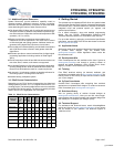
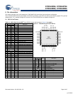
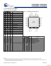
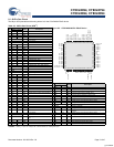
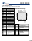
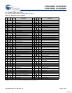
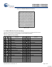
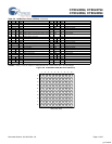
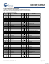
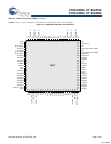
8.1 100-Ball VFBGA Part Pinout
The 100-ball VFBGA part is for the CY8C24994 PSoC device.
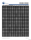
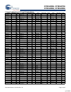
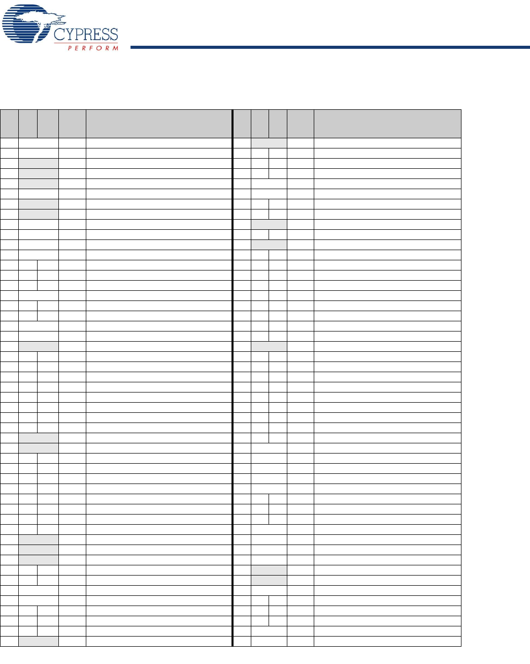
Table 8-5. 100-Ball Part Pinout (VFBGA)
Pin
No.
Digital
Analog
Name Description
Pin
No.
Digital
Analog
Name Description
A1 Power Vss Ground connection. F1 NC No connection.
A2 Power Vss Ground connection. F2 I/O M P5[7]
A3 NC No connection. F3 I/O M P3[5]
A4 NC No connection. F4 I/O M P5[1]
A5 NC No connection. F5 Power Vss Ground connection.
A6 Power Vdd Supply voltage. F6 Power Vss Ground connection.
A7 NC No connection. F7 I/O M P5[0]
A8 NC No connection. F8 I/O M P3[0]
A9 Power Vss Ground connection. F9 XRES Active high pin reset with internal pull down.
A10 Power Vss Ground connection. F10 I/O P7[1]
B1 Power Vss Ground connection. G1 NC No connection.
B2 Power Vss Ground connection. G2 I/O M P5[5]
B3 I/O I,M P2[1] Direct switched capacitor block input. G3 I/O M P3[3]
B4 I/O I,M P0[1] Analog column mux input. G4 I/O M P1[7] I2C Serial Clock (SCL).
B5 I/O I,M P0[7] Analog column mux input. G5 I/O M P1[1] I2C Serial Clock (SCL), ISSP SCLK
[1]
.
B6 Power Vdd Supply voltage. G6 I/O M P1[0] I2C Serial Data (SDA), ISSP SDATA
[1]
.
B7 I/O I,M P0[2] Analog column mux input. G7 I/O M P1[6]
B8 I/O I,M P2[2] Direct switched capacitor block input. G8 I/O M P3[4]
B9 Power Vss Ground connection. G9 I/O M P5[6]
B10 Power Vss Ground connection. G10 I/O P7[2]
C1 NC No connection. H1 NC No connection.
C2 I/O MP4[1] H2 I/O M P5[3]
C3 I/O MP4[7] H3 I/O M P3[1]
C4 I/O M P2[7] H4 I/O M P1[5] I2C Serial Data (SDA).
C5 I/O I/O,M P0[5] Analog column mux input and column output. H5 I/O M P1[3]
C6 I/O I,M P0[6] Analog column mux input. H6 I/O M P1[2]
C7 I/O I,M P0[0] Analog column mux input. H7 I/O M P1[4] Optional External Clock Input (EXTCLK).
C8 I/O I,M P2[0] Direct switched capacitor block input. H8 I/O M P3[2]
C9 I/O MP4[2] H9 I/O M P5[4]
C10 NC No connection. H10 I/O P7[3]
D1 NC No connection. J1 Power Vss Ground connection.
D2 I/O MP3[7] J2 Power Vss Ground connection.
D3 I/O MP4[5] J3 USB D+
D4 I/O M P2[5] J4 USB D-
D5 I/O I/O,M P0[3] Analog column mux input and column output. J5 Power Vdd Supply voltage.
D6 I/O I,M P0[4] Analog column mux input. J6 I/O P7[7]
D7 I/O M P2[6] External Voltage Reference (VREF) input. J7 I/O P7[0]
D8 I/O M P4[6] J8 I/O M P5[2]
D9 I/O M P4[0] J9 Power Vss Ground connection.
D10 NC No connection. J10 Power Vss Ground connection.
E1 NC No connection. K1 Power Vss Ground connection.
E2 NC No connection. K2 Power Vss Ground connection.
E3 I/O MP4[3] K3 NC No connection.
E4 I/O I,M P2[3] Direct switched capacitor block input. K4 NC No connection.
E5 Power Vss Ground connection. K5 Power Vdd Supply voltage.
E6 Power Vss Ground connection. K6 I/O P7[6]
E7 I/O M P2[4] External Analog Ground (AGND) input. K7 I/O P7[5]
E8 I/O M P4[4] K8 I/O P7[4]
E9 I/O M P3[6] K9 Power Vss Ground connection.
E10 NC No connection. K10 Power Vss Ground connection.
LEGENDA = Analog, I = Input, O = Output, M = Analog Mux Input, NC = No Connection.
[+] Feedback


