CY8C24094, CY8C24794
CY8C24894, CY8C24994
Document Number: 38-12018 Rev. *M Page 13 of 47
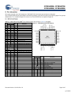
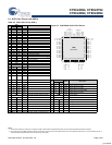
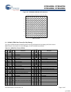
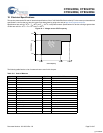
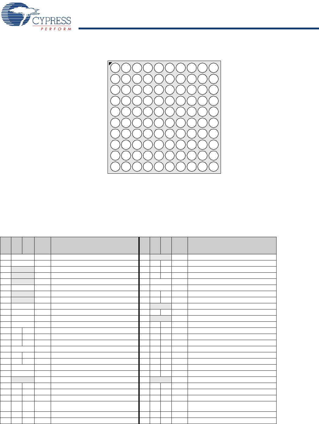
Figure 8-5. CY8C24094 OCD (Not for Production)
8.1 100-Ball VFBGA Part Pinout (On-Chip Debug)
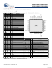
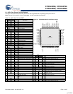
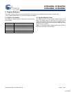
The 100-pin VFBGA part table and drawing below is for the CY8C24094 On-Chip Debug (OCD) PSoC device.
Note This part is only used for in-circuit debugging. It is NOT available for production.
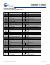
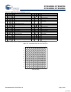
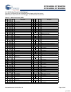
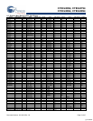
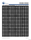
Table 8-6. 100-Ball Part Pinout (VFBGA)
Pin
No.
Digital
Analog
Name Description
Pin
No.
Digital
Analog
Name Description
A1 Power Vss Ground connection. F1 OCDE OCD even data I/O.
A2 Power Vss Ground connection. F2 I/O M P5[7]
A3 NC No connection. F3 I/O M P3[5]
A4 NC No connection. F4 I/O M P5[1]
A5 NC No connection. F5 Power Vss Ground connection.
A6 Power Vdd Supply voltage. F6 Power Vss Ground connection.
A7 NC No connection. F7 I/O M P5[0]
A8 NC No connection. F8 I/O M P3[0]
A9 Power Vss Ground connection. F9 XRES Active high pin reset with internal pull down.
A10 Power Vss Ground connection. F10 I/O P7[1]
B1 Power Vss Ground connection. G1 OCDO OCD odd data output.
B2 Power Vss Ground connection. G2 I/O M P5[5]
B3 I/O I,M P2[1] Direct switched capacitor block input. G3 I/O M P3[3]
B4 I/O I,M P0[1] Analog column mux input. G4 I/O M P1[7] I2C Serial Clock (SCL).
B5 I/O I,M P0[7] Analog column mux input. G5 I/O M P1[1] I2C Serial Clock (SCL), ISSP SCLK
[1]
.
B6 Power Vdd Supply voltage. G6 I/O M P1[0] I2C Serial Data (SDA), ISSP SDATA
[1]
.
B7 I/O I,M P0[2] Analog column mux input. G7 I/O M P1[6]
B8 I/O I,M P2[2] Direct switched capacitor block input. G8 I/O M P3[4]
B9 Power Vss Ground connection. G9 I/O M P5[6]
B10 Power Vss Ground connection. G10 I/O P7[2]
C1 NC No connection. H1 NC No connection.
C2 I/O MP4[1] H2 I/O M P5[3]
C3 I/O MP4[7] H3 I/O M P3[1]
C4 I/O M P2[7] H4 I/O M P1[5] I2C Serial Data (SDA).
C5 I/O I/O,
M
P0[5] Analog column mux input and column output. H5 I/O M P1[3]
C6 I/O I,M P0[6] Analog column mux input. H6 I/O M P1[2]
C7 I/O I,M P0[0] Analog column mux input. H7 I/O M P1[4] Optional External Clock Input (EXTCLK).
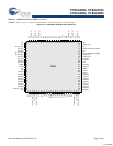
Vss Vss NC NC NC Vdd NC NC Vss Vss
Vss Vss P2[1] P0[1] P0[7] Vdd P0[2] P2[2] Vss Vss
NC P4[1] P4[7] P2[7] P0[5] P0[6] P0[0] P2[0] P4[2] NC
NC P3[7] P4[5] P2[5] P0[3] P0[4] P2[6] P4[6] P4[0] NC
NC NC P4[3] P2[3] Vss Vss P2[4] P4[4] P3[6] NC
NC P5[7] P3[5] P5[1] Vss Vss P5[0] P3[0] XRES P7[1]
NC P5[5] P3[3] P1[7] P1[1] P1[0] P1[6] P3[4] P5[6] P7[2]
NC P5[3] P3[1] P1[5] P1[3] P1[2] P1[4] P3[2] P5[4] P7[3]
Vss Vss D + D - Vdd P7[7] P7[0] P5[2] Vss Vss
Vss Vss NC NC Vdd P7[6] P7[5] P7[4] Vss Vss
12345678910
A
B
C
D
E
F
G
H
J
K
BGA (Top View)
[+] Feedback


