CYS25G0101DX-ATC Evaluation Board User’s Guide
12
5. Diagnostic Modes
The CYS25G0101DX Evaluation Board provides four different diagnostic modes—Diagnostic Loopback mode, Line Loopback
mode, Analog Loopback mode and “Parallel Line Loopback” mode. Figure 4 to Figure 7 illustrate these diagnostic modes and Figure
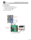
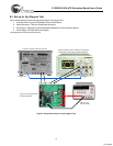
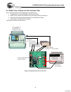
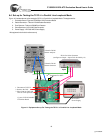
8 to Figure 10 illustrate the testing equipment set-up for testing the characteristics of the CYS25G0101DX.
5.1 Diagnostic Loopback Mode
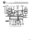
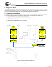
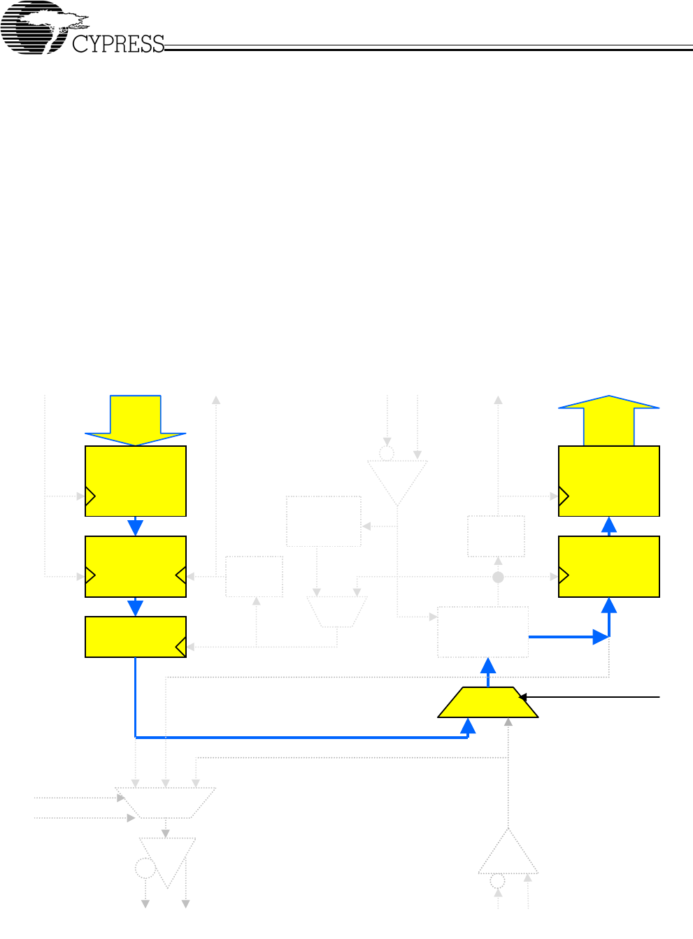
In the Diagnostic Loopback mode, parallel data will loop through the input buffer, serializer, CDR block, deserializer and the output buff-
er. Figure 4 shows the data path (bold line) of the Diagnostic Loopback mode. To select the Diagnostic Loopback mode:
1. SW1-2 (DIAGLOOP) must be in ON position, SW1-3 (LINELOOP)
2. All other dip switches must be in their default positions as stated in Table 4
3. TEST0, jumper J6 must be opened
4. Apply the Testing Hookup illustrated in Figure 8 to Figure 10
Figure 4. Diagnostic Loopback Mode Data Path
TXD
15:0
TX PLL
x16
/16
RXD
15:0
REFCLK
RXCLKOUT
SHIFTER
RX CDR
PLL
TXCLK
Input
Register
Output
Register
FIFO
(5byte)
SHIFTER
TXCLKIN
/16
DIAGLOOP
(SW1-2) = ON
LINELOOP
SW1-3 = OFF
LOOPA
SW1-4 = OFF
IN±
OUT±
[+] Feedback


