CYS25G0101DX-ATC Evaluation Board User’s Guide
6
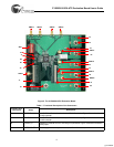
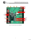
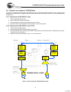
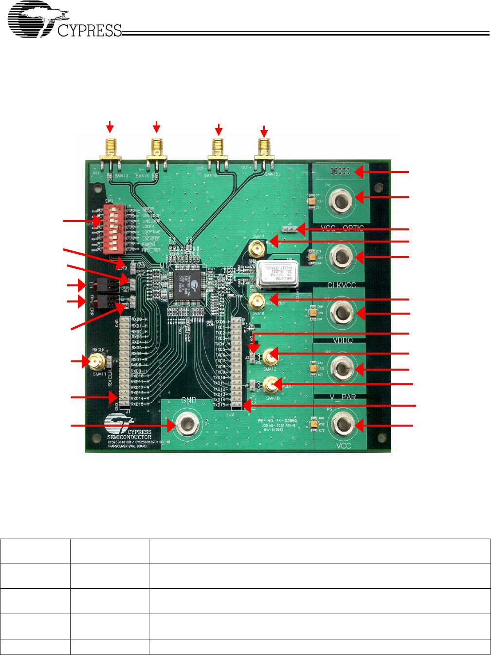
Figure 2. The CYS25G0101DX Evaluation Board
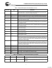
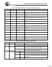
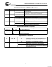
Table 1. Functional Description of the Connectors
Jumpers and
Connectors Name Description
J1 RxD BUS 16-bit RxD Data Bus interface header (see Table 2 for details). Figure 3 shows the orienta-
tion of this header
J2 TxD BUS 16-bit TxD Data Bus interface header (see Table 3 for details). Figure 3 shows the orienta-
tion of this header
J3 TxCLKO_H Header for CYS25G0101DX’s TXCLKO (pin 79) and GND. Figure 3 shows the orientation
of this jumper
J4 OPTIC POWER Power supply for external optical module (see Table 5 for details)
SMA13 SMA14
SMA16
SMA15
SW1
J7
D2
J8
J1
SMA11
P1
D1
J6
P4
J5
P5
SMA12
J3
P3
SMA18
P2
SMA17
SMA10
J2
P5
J4
[+] Feedback


