


STK17T88
Document Number: 001-52040 Rev. *A Page 18 of 22
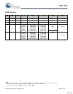
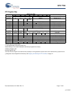
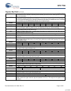
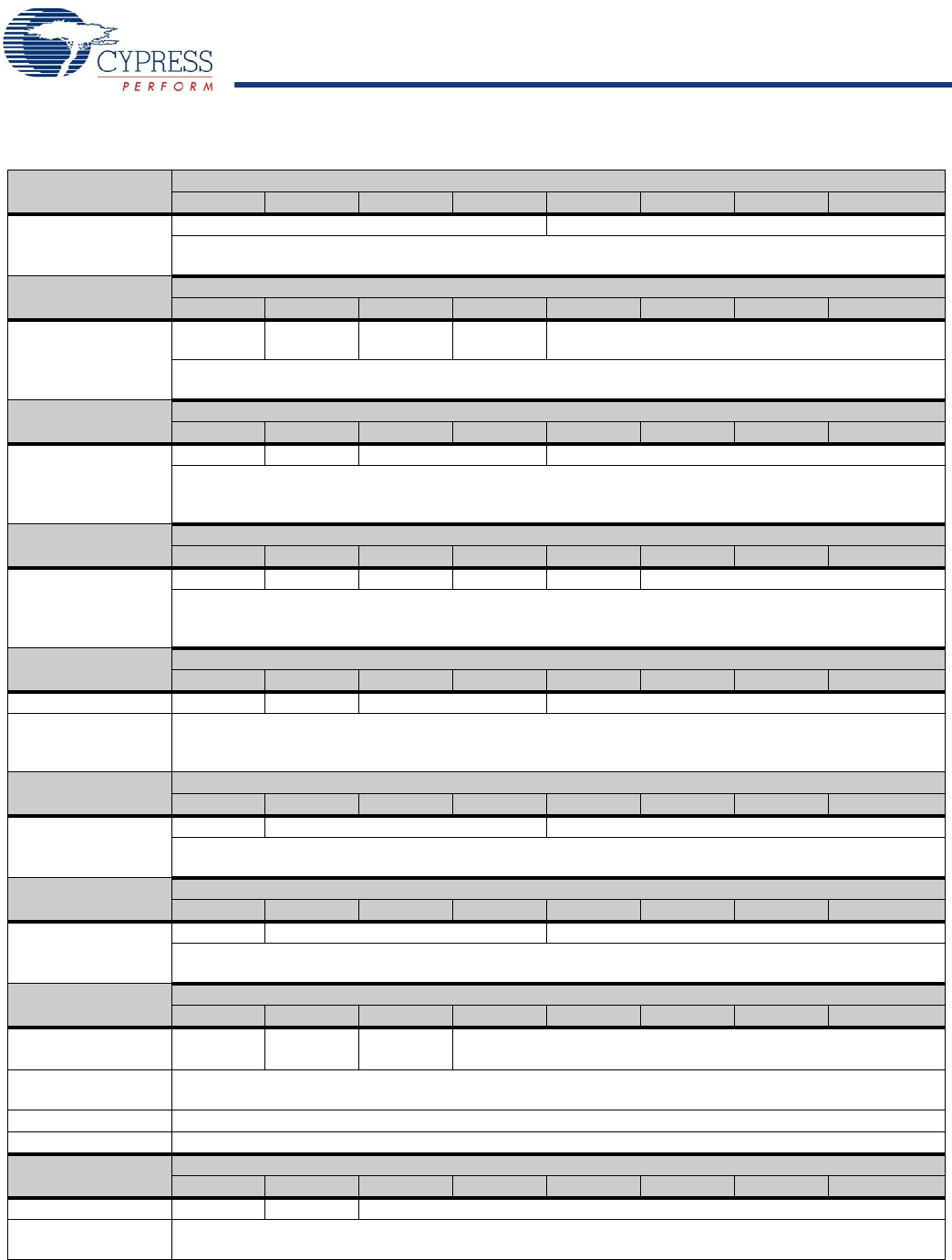
Register Map Detail
0x7FFF
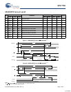
Real Time Clock – Years
D7 D6 D5 D4 D3 D2 D1 D0
10s Years Years
Contains the lower two BCD digits of the year. Lower nibble contains the value for years; upper nibble
contains the value for 10s of years. Each nibble operates from 0 to 9. The range for the register is 0-99.
0x7FFE
Real Time Clock – Months
D7 D6 D5 D4 D3 D2 D1 D0
0 0 0 10s
Month
Months
Contains the BCD digits of the month. Lower nibble contains the lower digit and operates from 0 to 9; upper
nibble (one bit) contains the upper digit and operates from 0 to 1. The range for the register is 1-12.
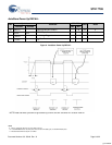
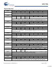
0x7FFD
Real Time Clock – Date
D7 D6 D5 D4 D3 D2 D1 D0
0 0 10s Day of month Day of month
Contains the BCD digits for the date of the month. Lower nibble contains the lower digit and operates from
0 to 9; upper nibble contains the upper digit and operates from 0 to 3. The range for the register is 1-31.
Leap years are automatically adjusted for.
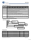
0x7FFC
Real Time Clock – Day
D7 D6 D5 D4 D3 D2 D1 D0
00000 Day of week
Lower nibble contains a value that correlates to day of the week. Day of the week is a ring counter that
counts from 1 to 7 then returns to 1. The user must assign meaning to the day value, as the day is not
integrated with the date.
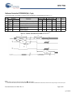
0x7FFB
Real Time Clock – Hours
D7 D6 D5 D4 D3 D2 D1 D0
0 0 10s Hours Hours
Contains the BCD value of hours in 24 hour format. Lower nibble contains the lower digit and operates
from 0 to 9; upper nibble (two bits) contains the upper digit and operates from 0 to 2. The range for the
register is 0-23.
0x7FFA
Real Time Clock – Minutes
D7 D6 D5 D4 D3 D2 D1 D0
0 10s Minutes Minutes
Contains the BCD value of minutes. Lower nibble contains the lower digit and operates from 0 to 9; upper
nibble contains the upper minutes digit and operates from 0 to 5. The range for the register is 0-59.
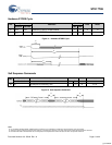
0x7FF9
Real Time Clock – Seconds
D7 D6 D5 D4 D3 D2 D1 D0
0 10s Seconds Seconds
Contains the BCD value of seconds. Lower nibble contains the lower digit and operates from 0 to 9; upper
nibble contains the upper digit and operates from 0 to 5. The range for the register is 0-59.
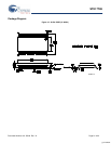
0x7FF8
Calibration
D7 D6 D5 D4 D3 D2 D1 D0
OSCEN 0 Calibratio
n Sign
Calibration
OSCEN Oscillator Enable. When set to 1, the oscillator is disabled. When set to 0, the oscillator is enabled.
Disabling the oscillator saves battery/capacitor power during storage.
Calibration Sign Determines if the calibration adjustment is applied as an addition to or as a subtraction from the time-base.
Calibration These five bits control the calibration of the clock.
0x7FF7
Watchdog Timer
D7 D6 D5 D4 D3 D2 D1 D0
WDS WDW WDT
WDS Watchdog Strobe. Setting this bit to 1 reloads and restarts the watchdog timer. The bit is cleared automat-
ically once the watchdog timer is reset. The WDS bit is write only. Reading it always will return a 0.
[+] Feedback