


DS1500
2
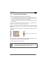
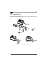
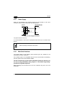
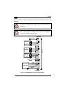
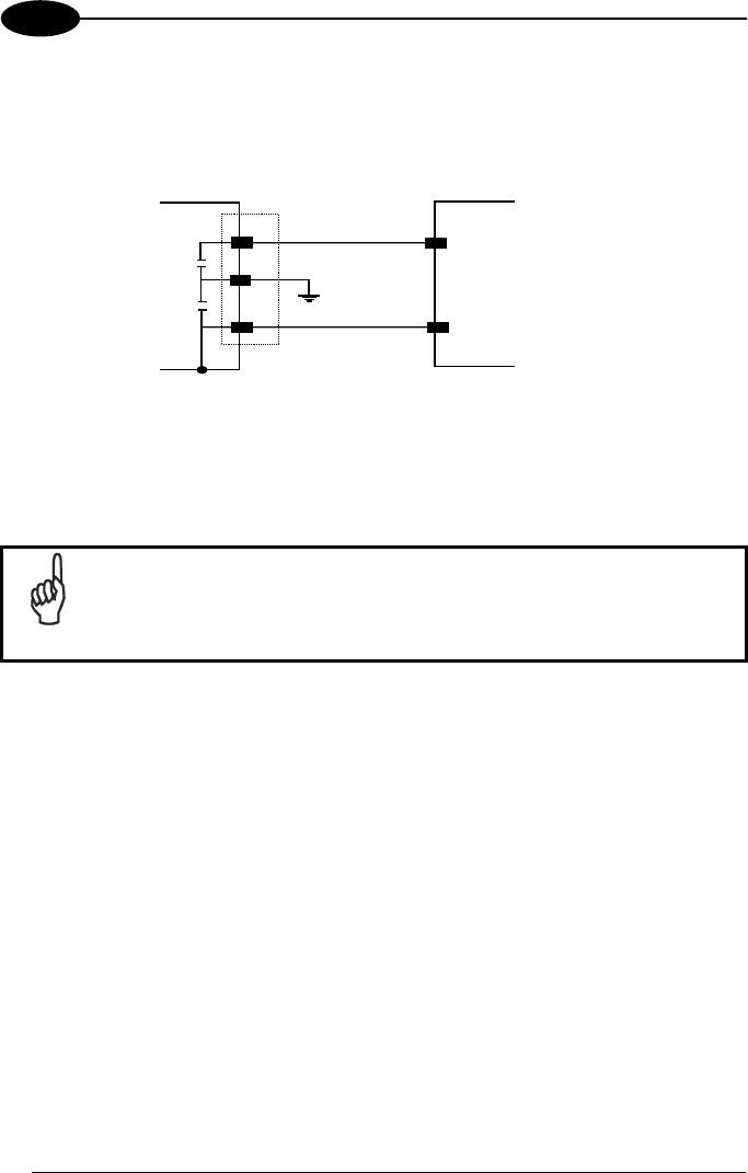
2.3.1 Power Supply
Power can be supplied to the scanner through the pins provided on the 15-pin
connector used for communication with the host (Figure 6):
1
8
5
VS
GND
USER INTERFACE
GND
V+ (5 Vdc)
DS1500
Earth Ground
Figure 6 - Power Supply Connections
The power must be 5 Vdc only.
It is recommended to connect pin 8 (Protective Earth Ground) to a common earth
ground.
NOTE
GND is internally connected to the chassis.
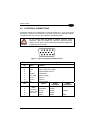
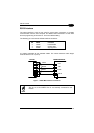
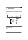
2.3.2 Main Serial Interface
The signals relative to the following serial interface types are available on the
input/output connector of DS1500.
If the interface type is not compatible with the current communication handshaking,
then the system forces the handshake to none.
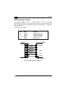
The main interface type and the relative parameters (baud rate, data bits, etc.)
can be set using the WinHost utility program or "Host Mode Programming”
procedure through ESC sequences.
Details regarding the connections and use of the interfaces are given in the next
paragraphs.
12