


INSTALLATION
2
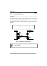
An anti-disturbance hardware filter is implemented on the External Trigger input (< 5
milliseconds delay).
An additional 15 ms (typical) delay can be implemented through a dedicated software
parameter (refer to WinHost Help On Line).
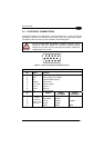
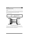
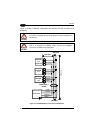
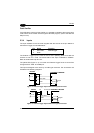
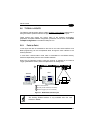
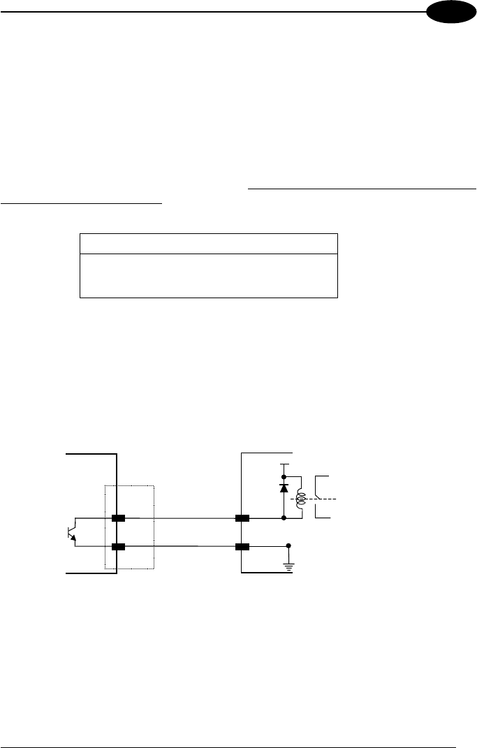
2.3.5 Outputs
Two general purpose outputs are available.
These outputs can only be connected as
open collector configurations. The following pins are present on the 15-pin connector
of the scanner:
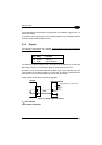
Pin Name Function
7 OUT1+ output 1 +
14 OUT2+ output 2 +
5 GND output reference
The meaning of the two outputs OUT1 and OUT2 can be defined by the user (No
Read, Right, Wrong, or a combination). Refer to the WinHost Help On Line.
By default, OUT1 is associated with the No Read event, which activates when the
code signaled by the external trigger is not decoded, and OUT2 is associated with
the Right event, which activates when the code is correctly decoded.
These outputs are both level and pulse configurable.
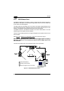
USER INTERFACE
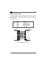
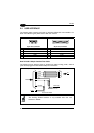
Vext 40Vdc max., 20 mA max.
DS1500
7/14
5
+
GND
Ground
Figure 14 - DS1500 Output Connections
V
CE
max = 40 Vdc
I max = 20 mA continuous
19