


DS1500
2
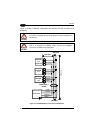
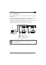
2.4 USER INTERFACE
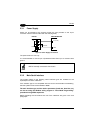
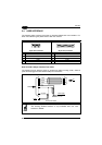
The following table contains the pinout for standard RS232 PC Host interface. For
other user interface types please refer to their own manual.
RS232 PC-side connections
1
5
9 6
9-pin male connector
13
25 14
1
25-pin male connector
Pin Name Pin Name
2 RX 3 RX
3 TX 2 TX
5 GND 7 GND
7 RTS 4 RTS
8 CTS 5 CTS
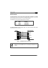
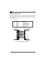
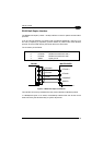
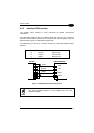
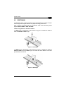
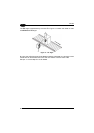
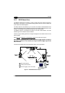
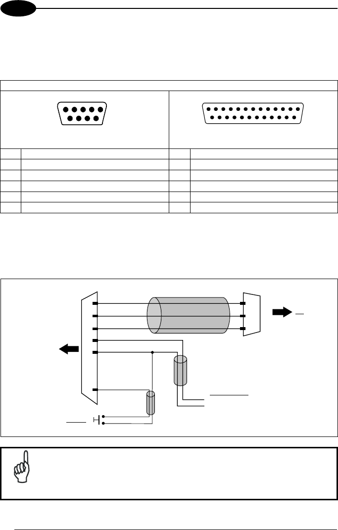
How To Build A Simple Interface Test Cable:
The following wiring diagram shows a simple test cable including power, external
(push-button) trigger and PC RS232 COM port connections.
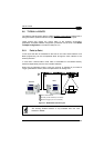
PC
15-pin D-sub high-density female
4
10
SGND
RXAUX
TXAUX
6
DS1500
5
1
GND
VS
9-pin D-sub female
GND
TX
RX
2
3
5
Power Supply
VS (5 Vdc)
Power GND
Trigger
EXT TRIG-
9
Test Cable for DS1500
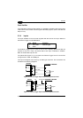
NOTE
The Auxiliary RS232 interface is only available when the main
interface is RS232.
20