INSTALLATION
2
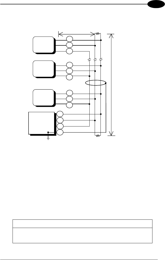
The following figure shows an example of a multidrop configuration between a
Multiplexer and DS2200 scanners.
120 Ohm
max. 1200 m.
RTX485 +
RTX485 -
Three wires + shield
MULTIPLEXER
# 1
DS2200
RTX485+
RTX485-
SGND
# 0
DS2200
DS2200
# x
(up to 31)
120 Ohm
max. 2 m.
7
4
5
RS485 REF
7
4
5
7
4
5
SHIELD
Figure 6 - DS2200 Multidrop connection to a Multiplexer
2.3.3 Auxiliary Interface - RS232
The auxiliary serial interface is used exclusively for RS232 point-to-point
connections. It is also used for configuring the DS2200.
The parameters relative to the auxiliary interface (baud rate, data bits, etc.) can be
defined using the WinHost utility program or "Host Mode Programming" installed from
the diskette.
The following pins of the 25-pin connector are used to connect the RS232 auxiliary
interface:
Pin Name Function
3 RXAUX RS232 received data
2 TXAUX RS232 transmitted data
7 SGND signal ground
9


