INSTALLATION
2
2.5 TYPICAL LAYOUTS
The following typical layouts refer to system
hardware configurations. Dotted lines in
the figures refer to optional hardware configurations within the particular layout.
These layouts also require the correct setup of the software configuration
parameters. Complete software configuration procedures can be found in the Guide
To Rapid Configuration in the WinHost Help On Line.
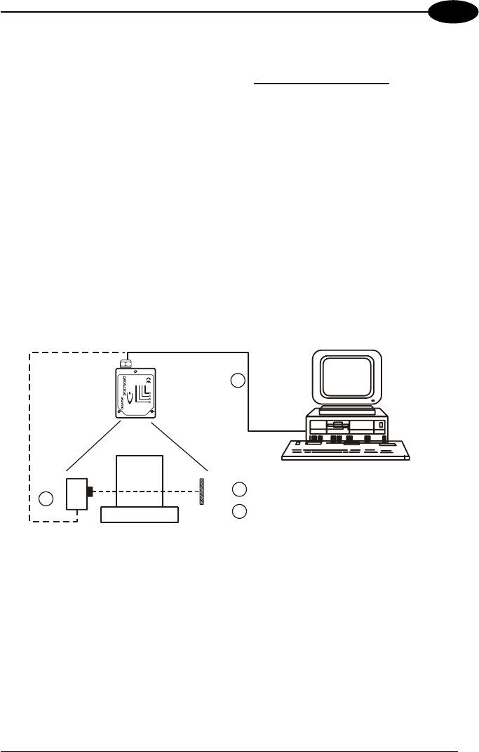
2.5.1 Point-to-Point
In this layout data is transmitted to the Host on the RS232 Auxiliary serial interface.
The Local Echo communication mode must be enabled (default) see the WinHost
Help On Line.
When On-Line Operating mode is used, the scanner is activated by an External
Trigger (photoelectric sensor) when the object enters its reading zone.
1
2
1
2
Auxiliary serial interface
External Trigger (for On-Line mode)
H
ost
DS2200
TX DATA
EXT TRIG
GOOD READ
POWER ON
Figure 13 - Point to Point layout
2.5.2 RS485 Master/Slave
The RS485 Master/Slave connection is used to collect data from several scanners to
build a multi-point or a multi-sided reading system; there can be one Master and up
to 5 Slaves connected together.
The Slave scanners are connected together using the RS485 half-duplex main serial
interface. Every Slave scanner must have a multidrop address in the range 0-4.
13


