


INSTALLATION
2
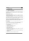
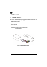
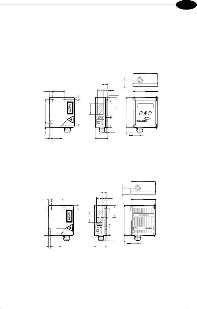
2.2 MECHANICAL INSTALLATION
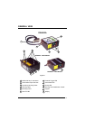
DS4600A can be installed to operate in different positions. The four screw holes
(M4 x 5) on the body of the reader are for mechanical fixture (Figure A, 5).
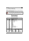
The diagram below gives the overall dimensions of the scanner and may be used for
its installation.
Refer to paragraph 2.4 for correct positioning.
10
0.39
41.8
1.64
M4 N° 4
37
1.47
5
0.2
11.8
0.46
81
3.19
8.25
0.32
87.9
3.46
M4 N°2
58
2.28
32.5
1.28
3.75
0.15
42
1.65
20
0.79
83.5
3.29
101
3.98
18
0.70
0.90
23
DS4600A
37
20.2
1.46
22*
0.86
0.8
14.8
0.58
39.4
1.55
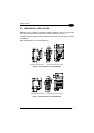
* The quote refers to the scan lineMounting hole depth M4 X 5
Figure 2 - Overall Dimensions for 2XXX Models
10
0.39
41.8
1.64
M4 N° 4
37
1.47
5
0.2
11.8
0.46
81
3.19
8.25
0.32
87.9
3.46
M4 N°2
58
2.28
32.5
1.28
3.75
0.15
42
1.65
37
20.2
1.46
18*
0.71
0.8
14.8
0.58
39.4
1.55
0.90
0.70
18
23
101
3.98
20
0.79
3.29
83.5
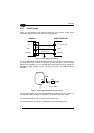
* The quote refers to the scan line
Mounting hole depth M4 X 5
Figure 3 - Overall Dimensions for 3XXX Models
5