


DS4600A
2
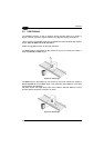
2.3.4 Inputs
There is an input available on the DS4600A scanner relative to the External Trigger.
There are also 2 general purpose inputs:
IN1 can be used to store the code verifier (see "Store verifier HW" in the WinHost
Help On Line).
IN2 can be used as the Reading Field Control signal which determines either
the
Code Reading Condition or
the Code Resolution parameter for each reading phase.
Refer to the WinHost Help On Line.
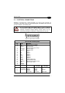
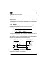
The pinouts are indicated below:
Pin Name Function
18 EXT TRIG+ external trigger +
19 EXT TRIG- external trigger -
6 IN1+ input 1 +
10 IN1- input 1 -
14 IN2+ input 2 +
15 IN2- input 2 -
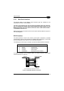
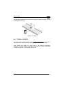
The EXT TRIG inputs are used in the On-Line Operating mode and tells the scanner
to scan for a code. The active state of this input is selected in software. Refer to the
WinHost Help On Line. The yellow led, (Figure A, 7), is on when the External Trigger
signals the active reading phase.
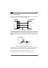
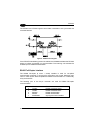
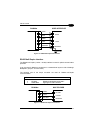
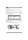
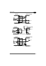
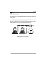
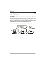
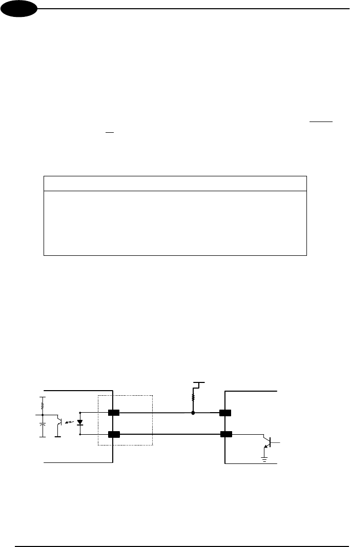
These inputs are optocoupled and can be driven by both an NPN or PNP type
command. The connections are indicated in the following diagrams:
18/6/14
+
19/10/15
-
USER INTERFACE DS4600
A
+ 5V
Signal
V
30 Vdc max.
Vext
Figure 14 - Input NPN Command Using External Power
14